Part Two - The Restoration
1971 10 " F/6 Custom Super Deluxe
by Jon Miles
Click on any image for larger size
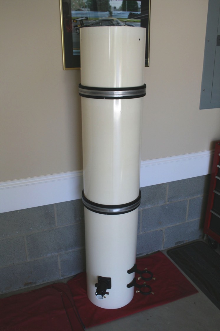
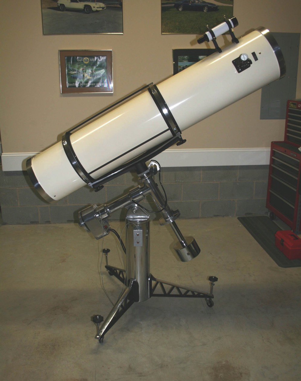
No doubt this 1971 Cave 10” Custom Super Deluxe is a beautiful instrument. But over the years the chrome plated steel parts started pitting and the polished aluminum had lost its luster. I decided I wouldn’t be satisfied unless I did a complete refurbishment on it.
Cave telescopes and mounts are really quite easy to disassemble for anyone with some mechanical skills and tools. And if you get stuck on anything there are lots of folks on the Cloudy Nights Classic Telescope forum ready to help.
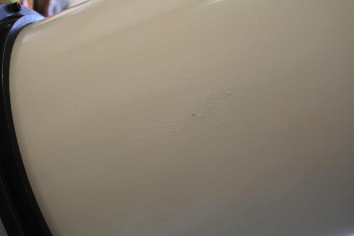
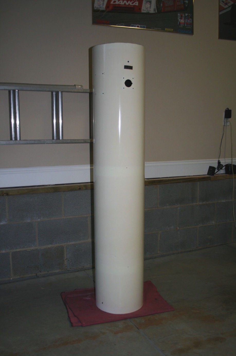
My first concern was whether to refinish the main tube. These fiberglass tubes are prone to cracking and the outer gel coat layer can begin to lift. If left unchecked it can start to chip away. Cave referred to the finish on tubes from this era as “Porcelainized”. It is an off white color that is almost a gloss finish. You can see the weaving of the fiberglass mat but the finish is not rough by any means.
My scope has a couple of areas that have stress cracks. But since there would be no way to reproduce the original finish by painting, I decided that these stress cracks were just not enough to justify refinishing the tube. I did use some of the liquid, flowable super glue at the ends of some of the cracks to stabilize them and hopefully keep them from getting worse or have any of the gel coat break off.
Cave telescopes and mounts are really quite easy to disassemble for anyone with some mechanical skills and tools. And if you get stuck on anything there are lots of folks on the Cloudy Nights Classic Telescope forum ready to help.
My first concern was whether to refinish the main tube. These fiberglass tubes are prone to cracking and the outer gel coat layer can begin to lift. If left unchecked it can start to chip away. Cave referred to the finish on tubes from this era as “Porcelainized”. It is an off white color that is almost a gloss finish. You can see the weaving of the fiberglass mat but the finish is not rough by any means.
My scope has a couple of areas that have stress cracks. But since there would be no way to reproduce the original finish by painting, I decided that these stress cracks were just not enough to justify refinishing the tube. I did use some of the liquid, flowable super glue at the ends of some of the cracks to stabilize them and hopefully keep them from getting worse or have any of the gel coat break off.
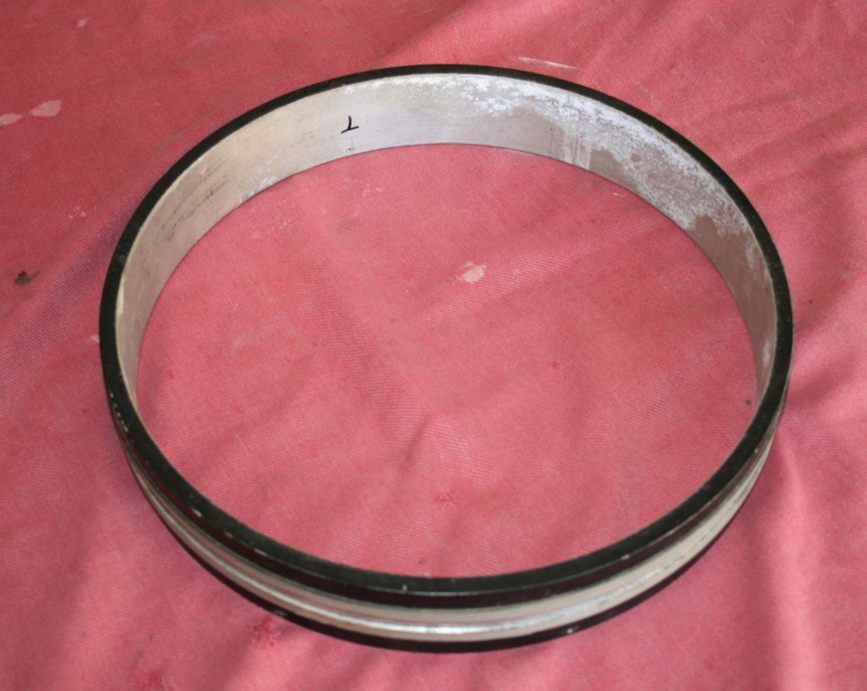
One area of caution when disassembling would be sliding the inner tube rings off of the tube. There is the potential that they could leave scratches when sliding down the tube. It is a good idea to wax the tube first. Some powder can also be sprinkled on the tube, trying to get some under the rings. These steps should help them come off smoothly. Longer focal lengths are a greater challenge and always remember to take the shorter route (toward the mirror end).
Mine also had a powdery aluminum corrosion on the inside which actually helped during removal.
Mine also had a powdery aluminum corrosion on the inside which actually helped during removal.
One problem this scope developed immediately after I brought it home was the 360 degree declination drive stopped working. I could hear the motor run in both directions but the scope was not slewing.
Disassembling the declination shaft has to be done carefully. First remove the counterweight and setting circle. Then loosen the set screw the holds the declination drive mounting plate to the declination shaft. Now loosen but don’t remove the large socket head bolt that holds the cradle to the declination shaft. Once you remove this bolt the declination shaft will be free to drop out the bottom. A friend can be useful here to hold the shaft. Once the bolt is out remove the cradle. You can now remove the declination drive and support bearing from the top of the shaft and slide the shaft out the bottom.
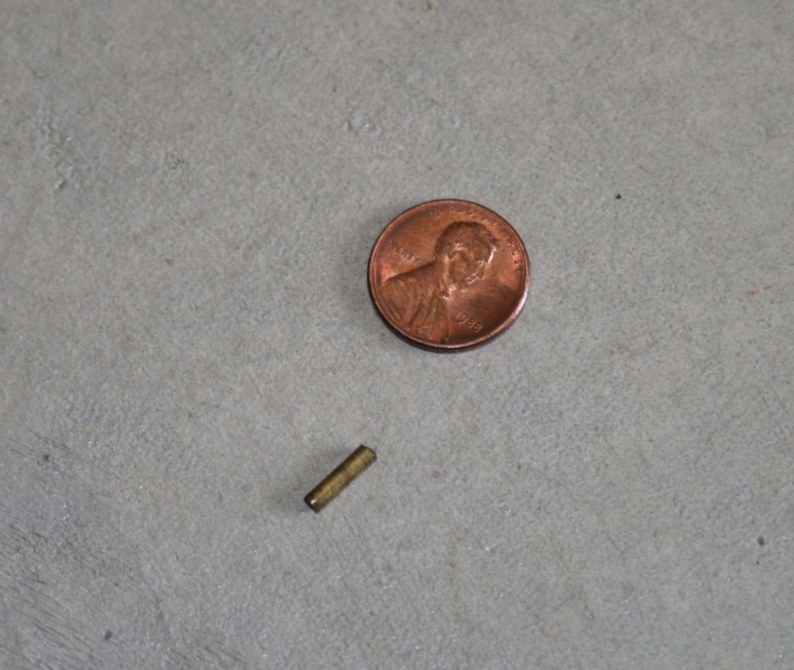
When I went to remove the declination drive a tiny brass pin fell out. I looked at the drive for a bit but didn’t see where it went. I bagged it up knowing that I’d find where it went when I later disassembled the drive.
Disassembling the declination shaft has to be done carefully. First remove the counterweight and setting circle. Then loosen the set screw the holds the declination drive mounting plate to the declination shaft. Now loosen but don’t remove the large socket head bolt that holds the cradle to the declination shaft. Once you remove this bolt the declination shaft will be free to drop out the bottom. A friend can be useful here to hold the shaft. Once the bolt is out remove the cradle. You can now remove the declination drive and support bearing from the top of the shaft and slide the shaft out the bottom.
When I went to remove the declination drive a tiny brass pin fell out. I looked at the drive for a bit but didn’t see where it went. I bagged it up knowing that I’d find where it went when I later disassembled the drive.
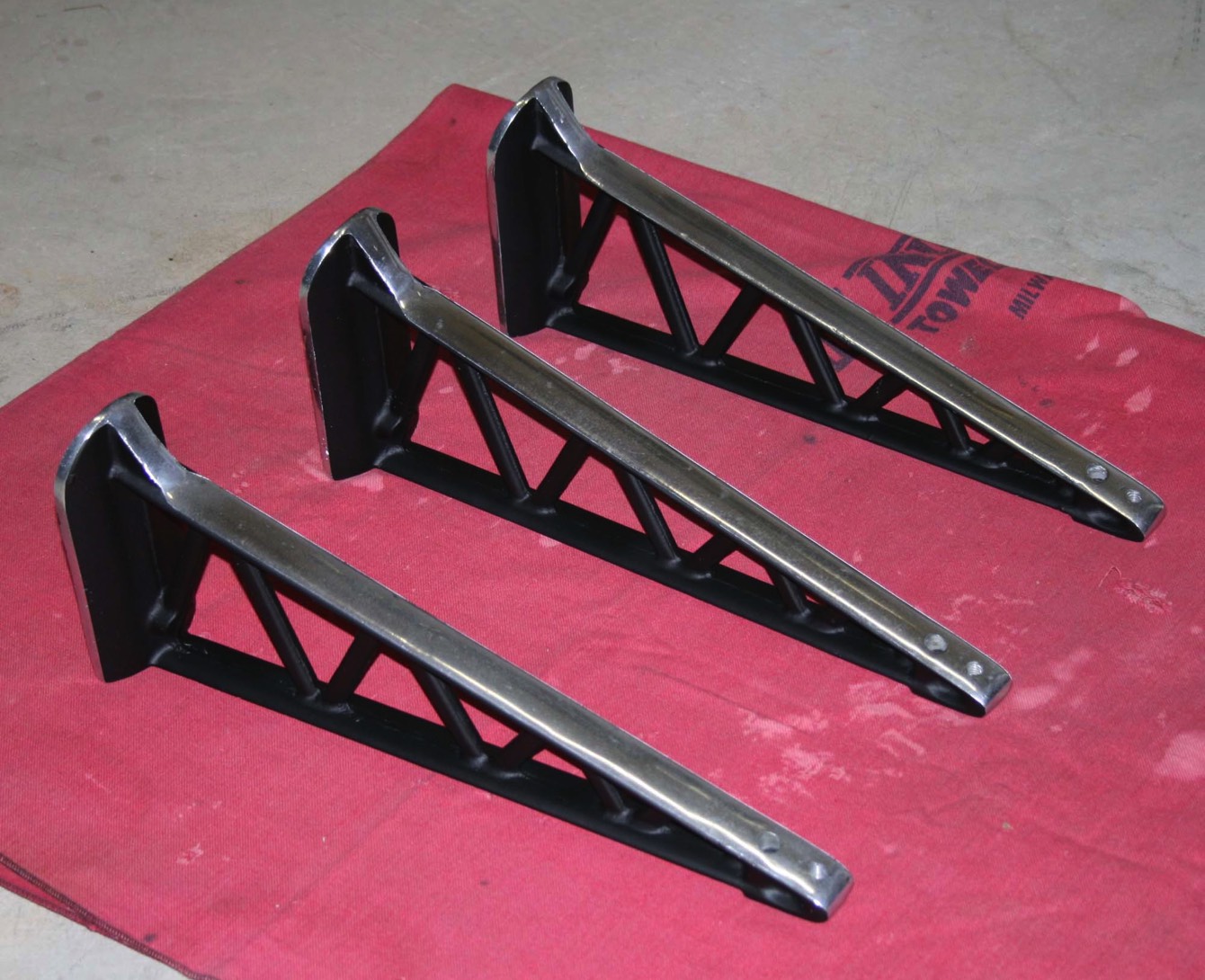
I then worked on stripping the parts that had some flat black paint on them – the inner tube rings, OTA saddle, tube ring spacer rods, outer tube rings, pier legs and the declination and RA setting circle pointers. Normally I would bead blast these to strip them but, since many of these parts had polished edges, I needed to chemically strip them since bead blasting would rough up the polished surfaces.
The first two pieces I finished were the declination and RA setting circle pointers. Here they are after masking, priming and repainting. The final finish is Rustoleum Flat Black.
The first two pieces I finished were the declination and RA setting circle pointers. Here they are after masking, priming and repainting. The final finish is Rustoleum Flat Black.
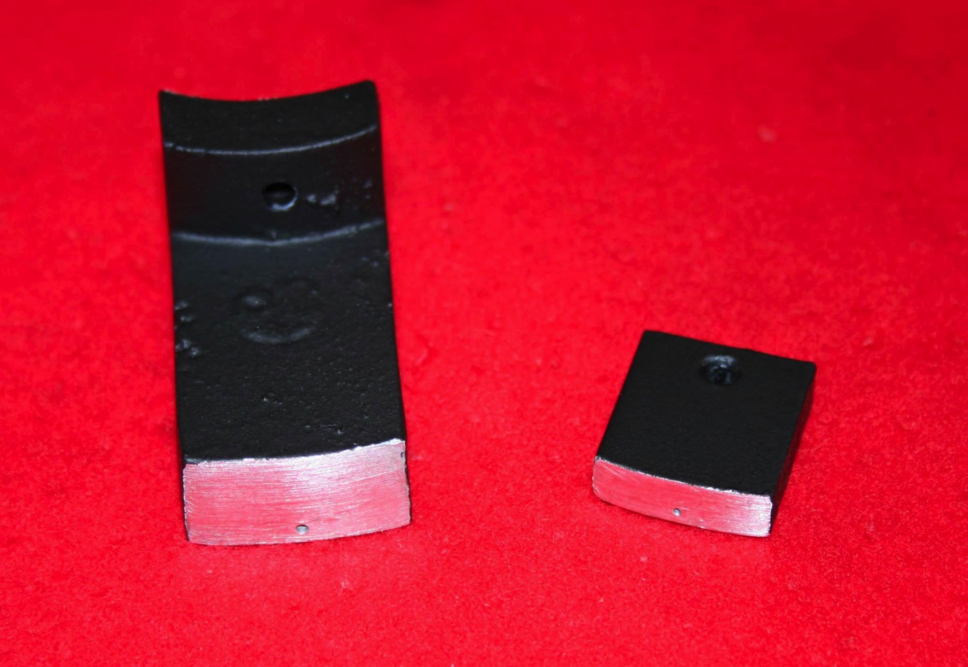
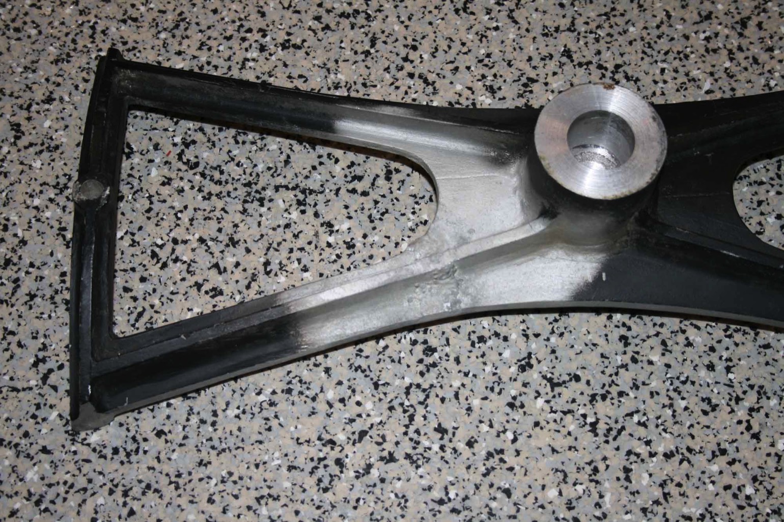
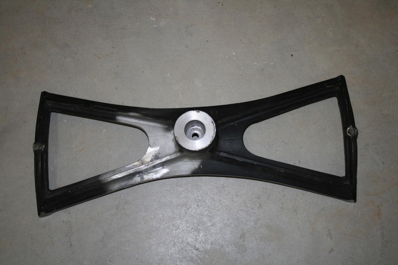
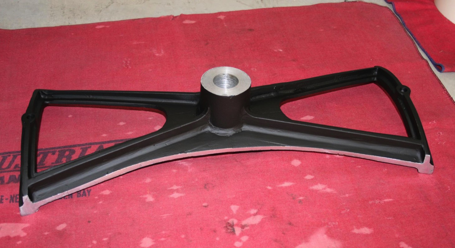
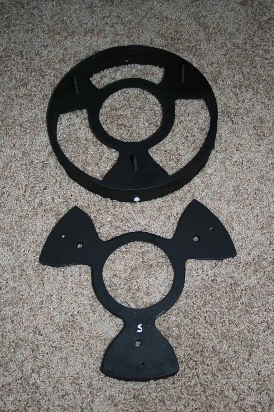
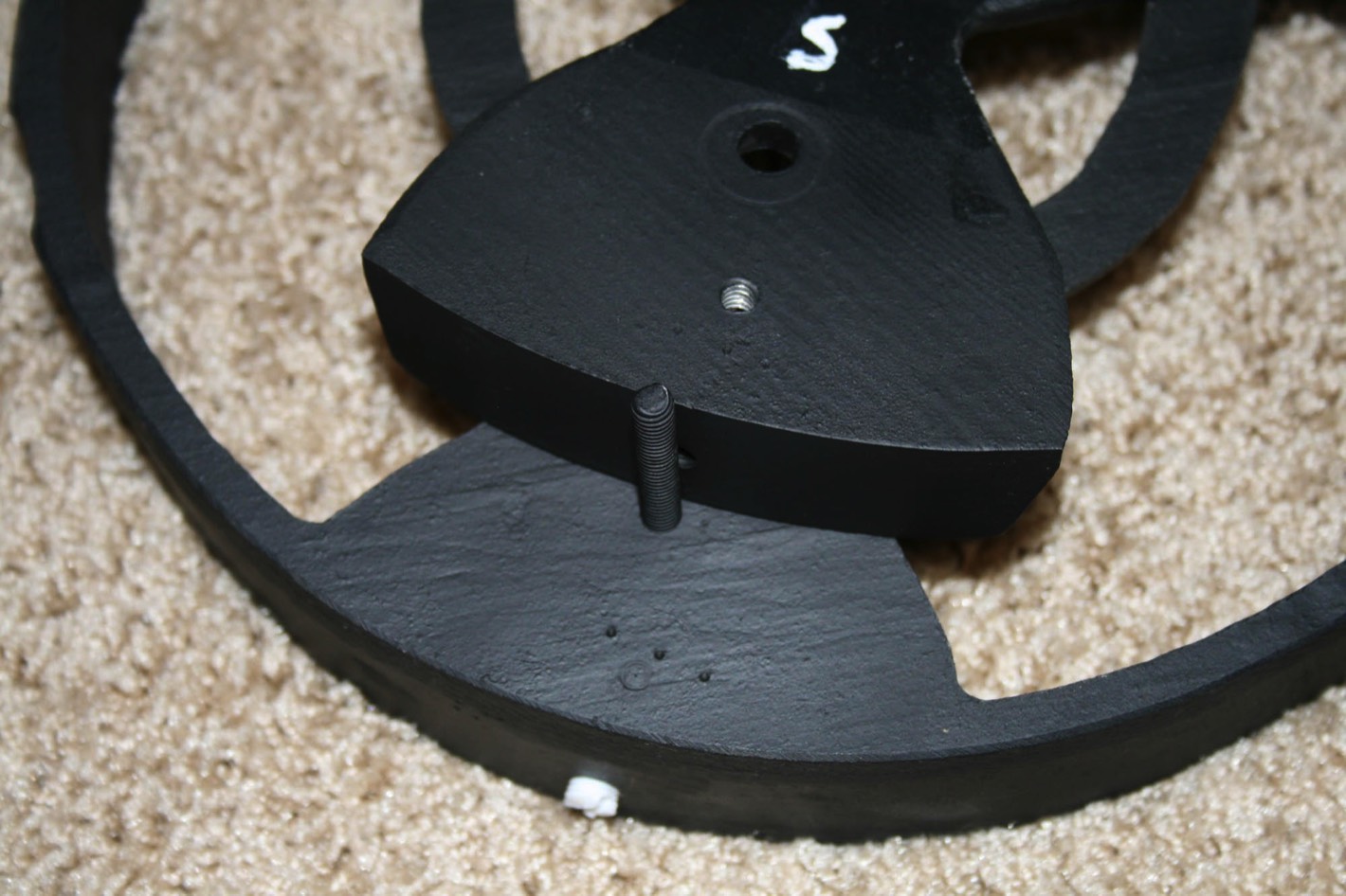
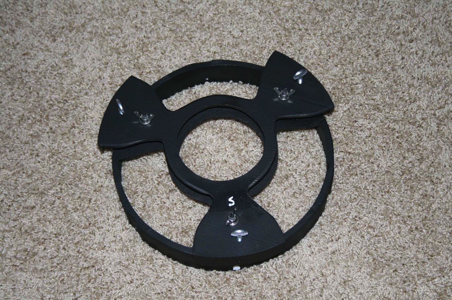
Next I worked on the mirror cell. I didn’t want to completely strip the three legged support since it had a hand painted “S” on one leg to indicate which leg was aligned with the tube Seam when reinstalling the cell. I have seen this S painted on other (though not all) Cave mirror cells so I assume it was done at the factory.
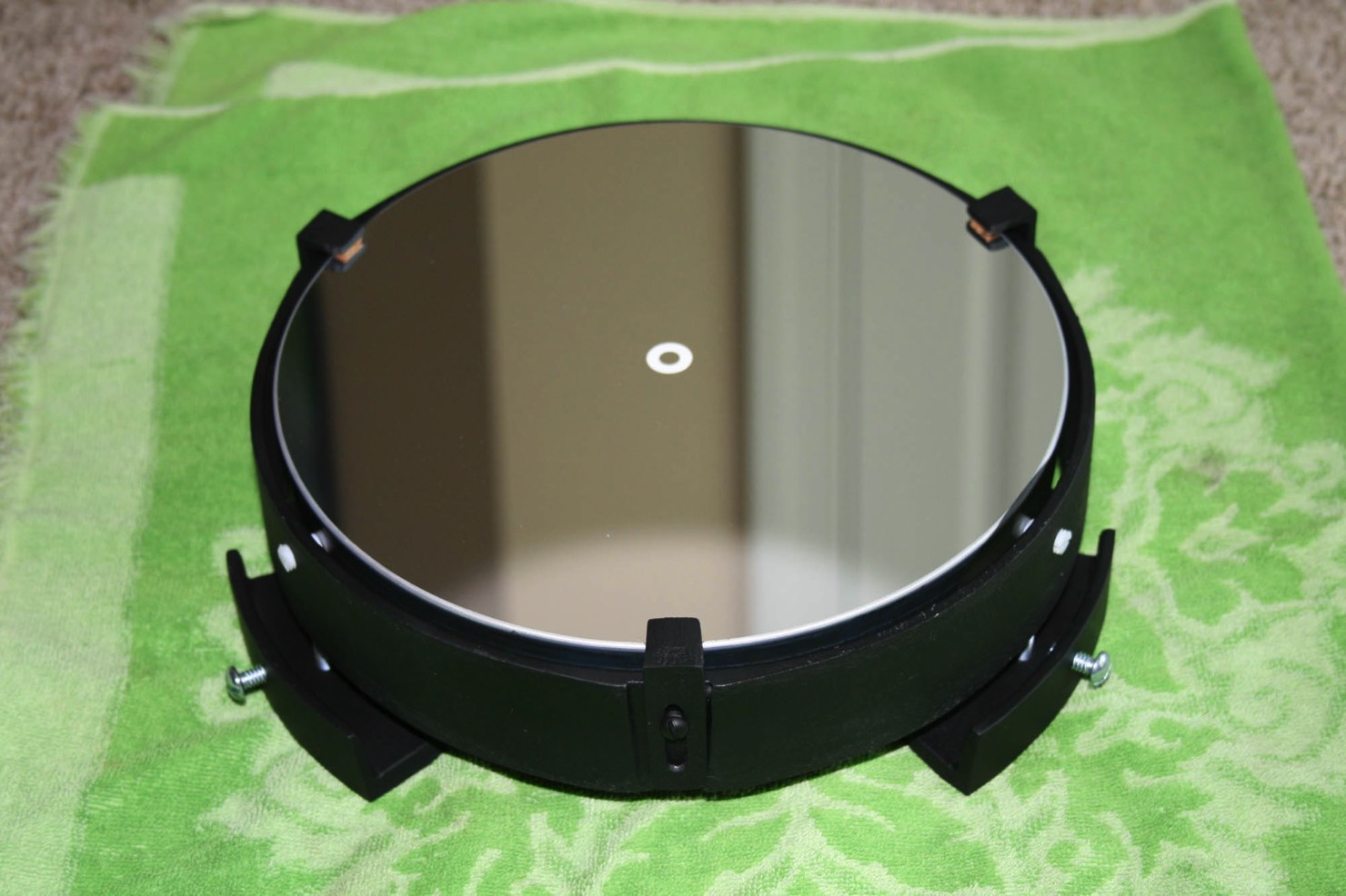
The mirror was given a cleaning with distilled water, a few drops of Dawn dish washing liquid and surgical cotton balls. After rinsing with more distilled water, it was finally wiped down with 99% isopropyl alcohol and a soft cotton cloth.
Here it is back in its home with refinished mirror retaining clips.
Here it is back in its home with refinished mirror retaining clips.
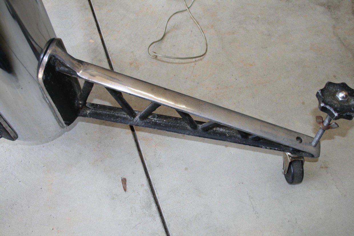
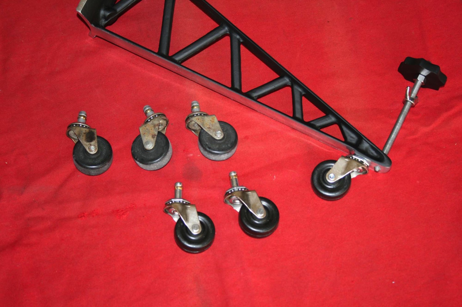
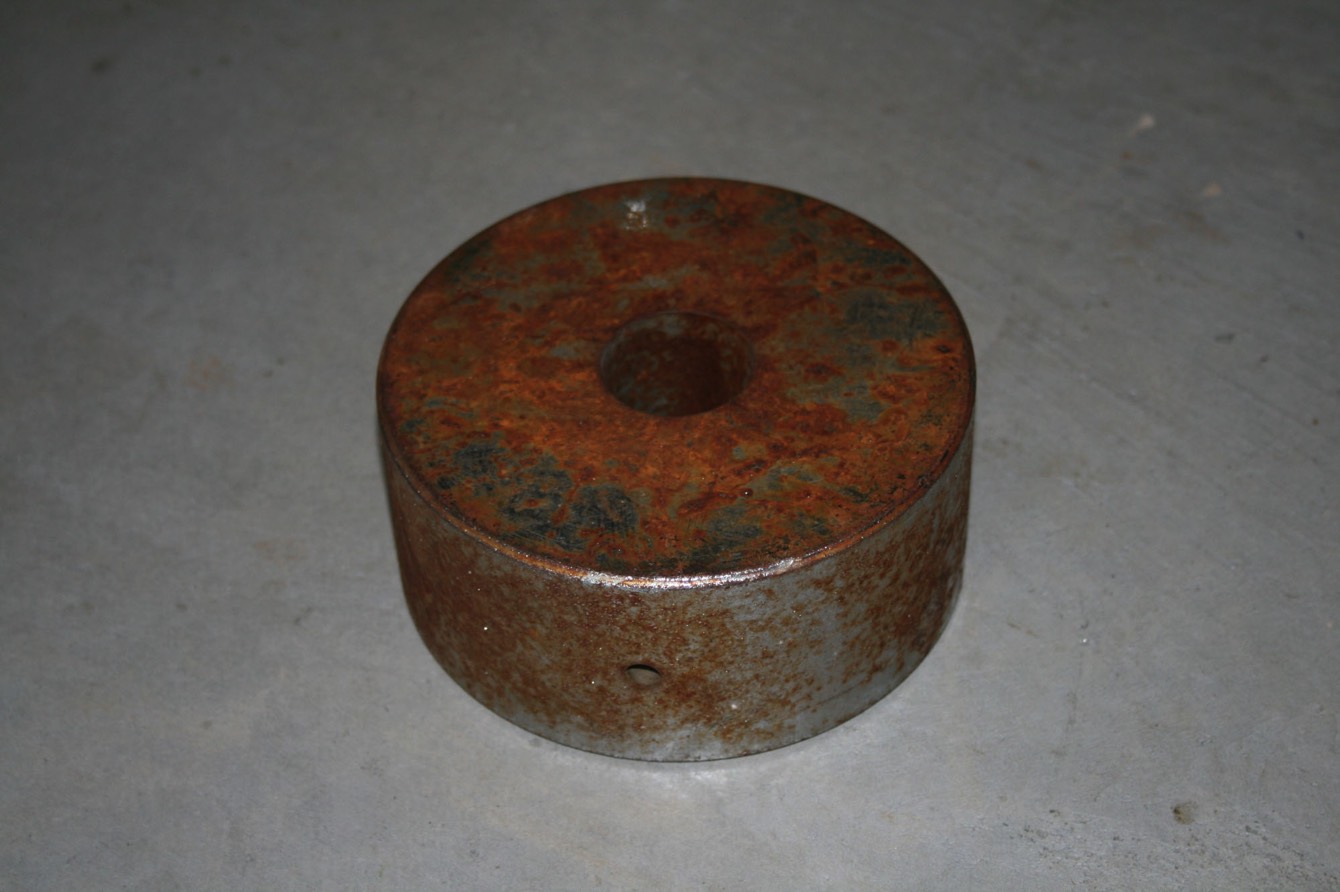
The casters on the legs were in rough shape. The nickel plating was pitted and they were fairly worn out. The originals were made by Noelting Faultless Caster. They are 2” diameter with a 1” long friction grip stem which is 7/16” diameter. Noelting Faultless Caster is still in business but a call to them found they have a $100 minimum order, which would have been 25 casters!
So I searched around for another replacement. Ace Hardware #9193 is close but the stem is 1 3/8” long and would have stuck out the top of the leg. I ordered McMaster-Carr number 2391T1 and these were perfect.
So I searched around for another replacement. Ace Hardware #9193 is close but the stem is 1 3/8” long and would have stuck out the top of the leg. I ordered McMaster-Carr number 2391T1 and these were perfect.
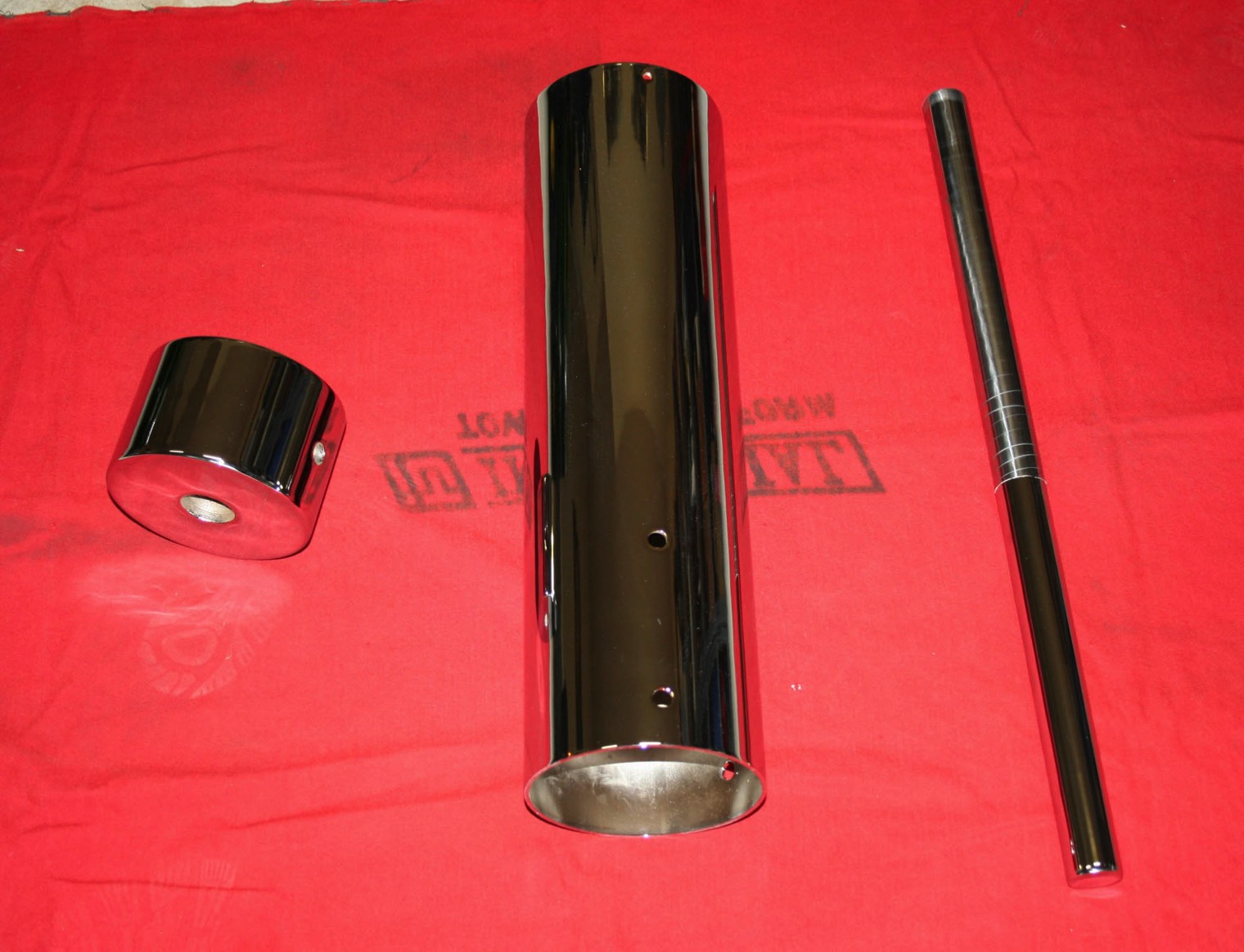
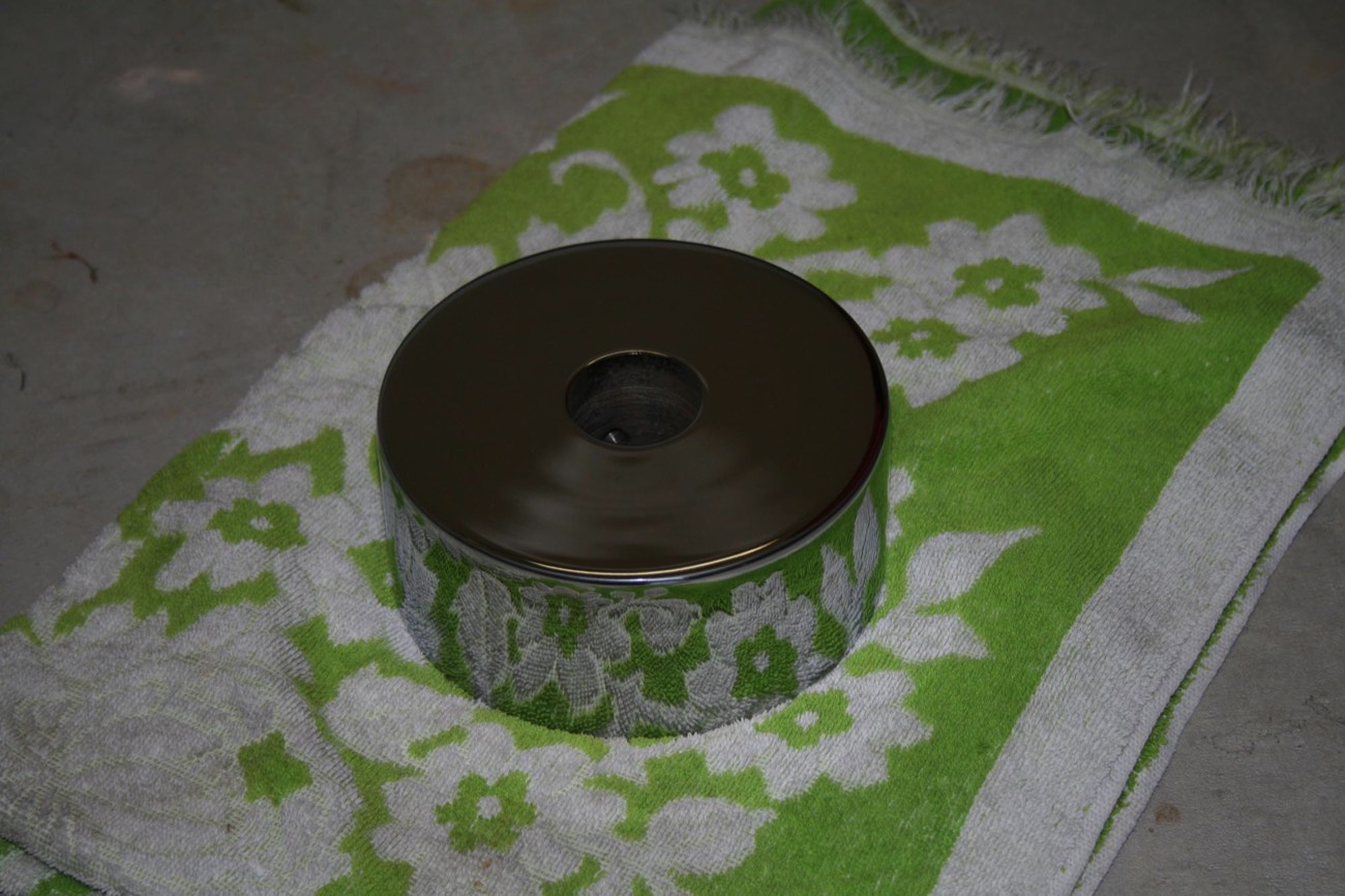
Three parts, which are steel, are chrome plated. It seems to be becoming difficult to find firms doing show chrome plating. A lot of them have been shut down by the EPA for less than safe handling of the chemicals used.
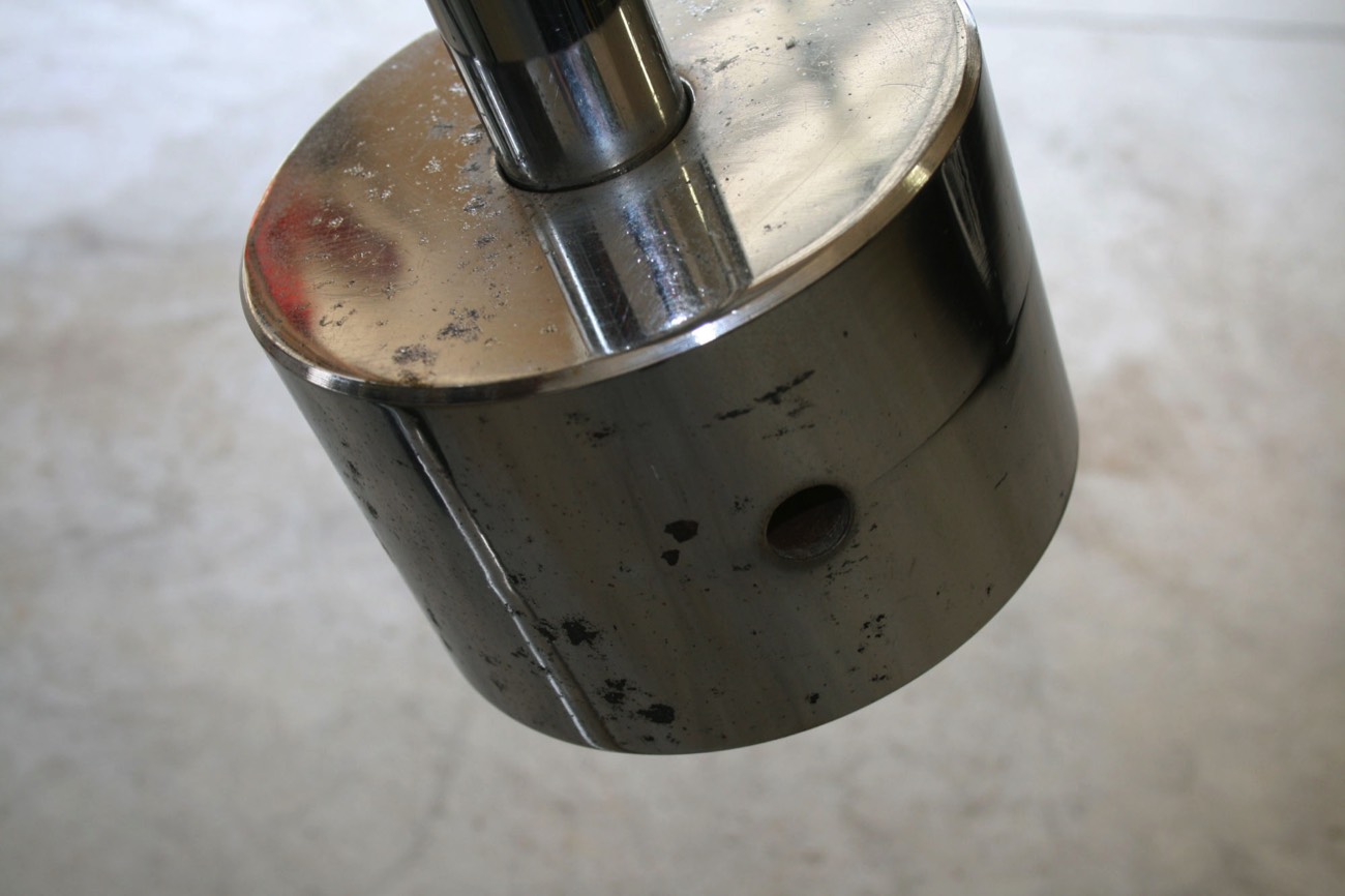
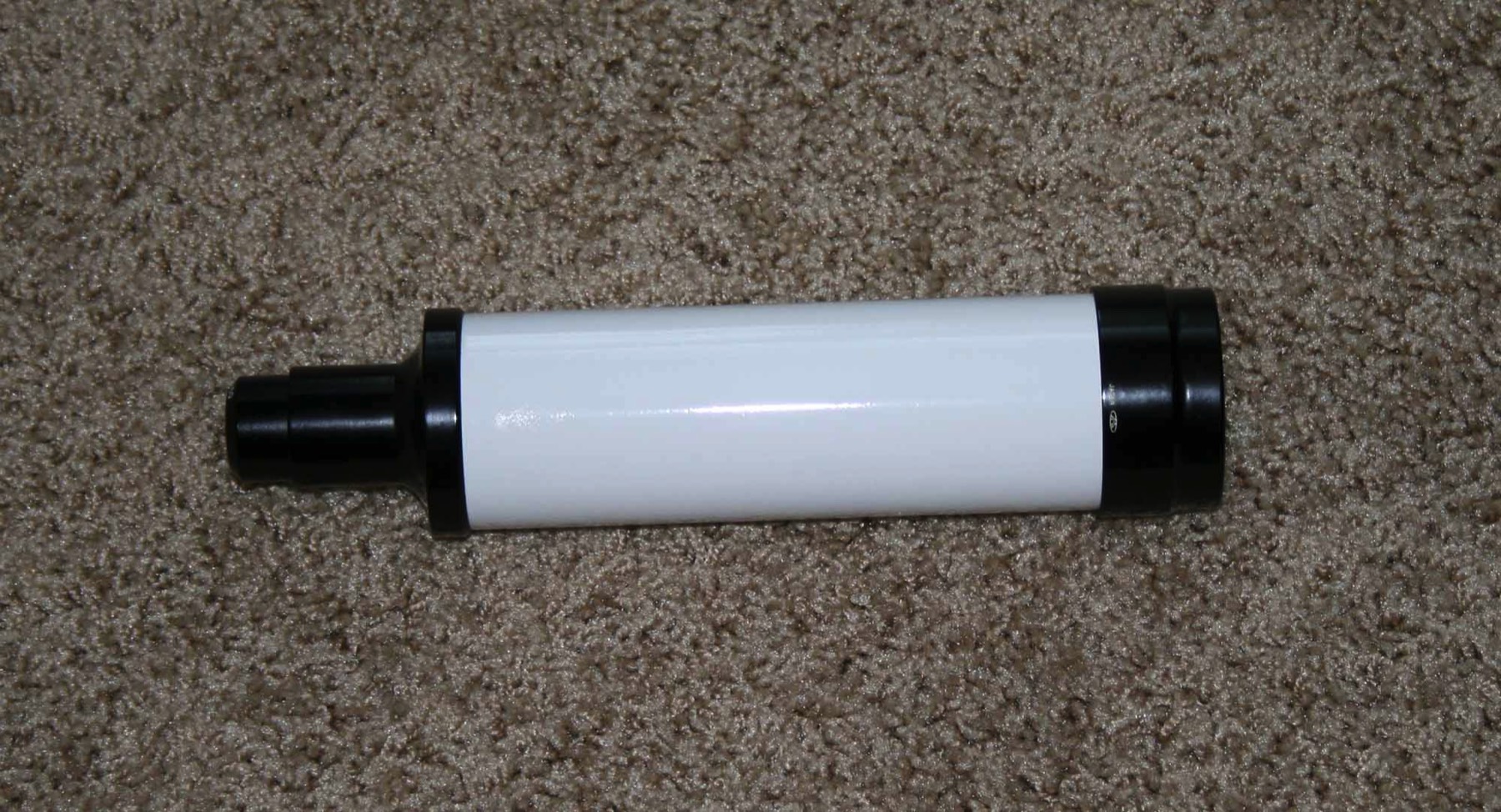
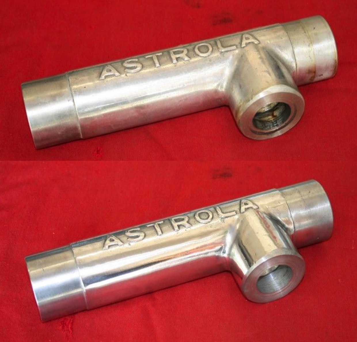
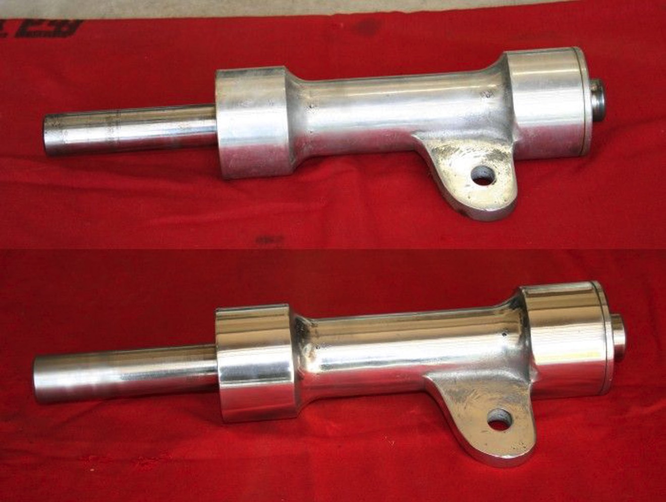
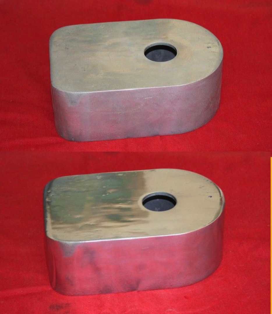
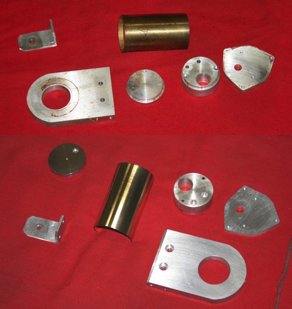
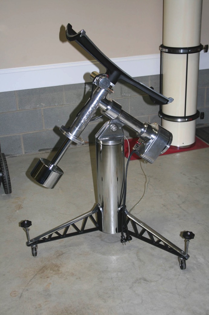
Here is the counterweight, pier tube and declination shaft after re-plating. Only the lower 12” of the declination shaft are chrome plated as the plating would be too thick to properly fit in the declination shaft bearings.
Here is the counterweight, pier tube and declination shaft after re-plating. Only the lower 12” of the declination shaft are chrome plated as the plating would be too thick to properly fit in the declination shaft bearings.
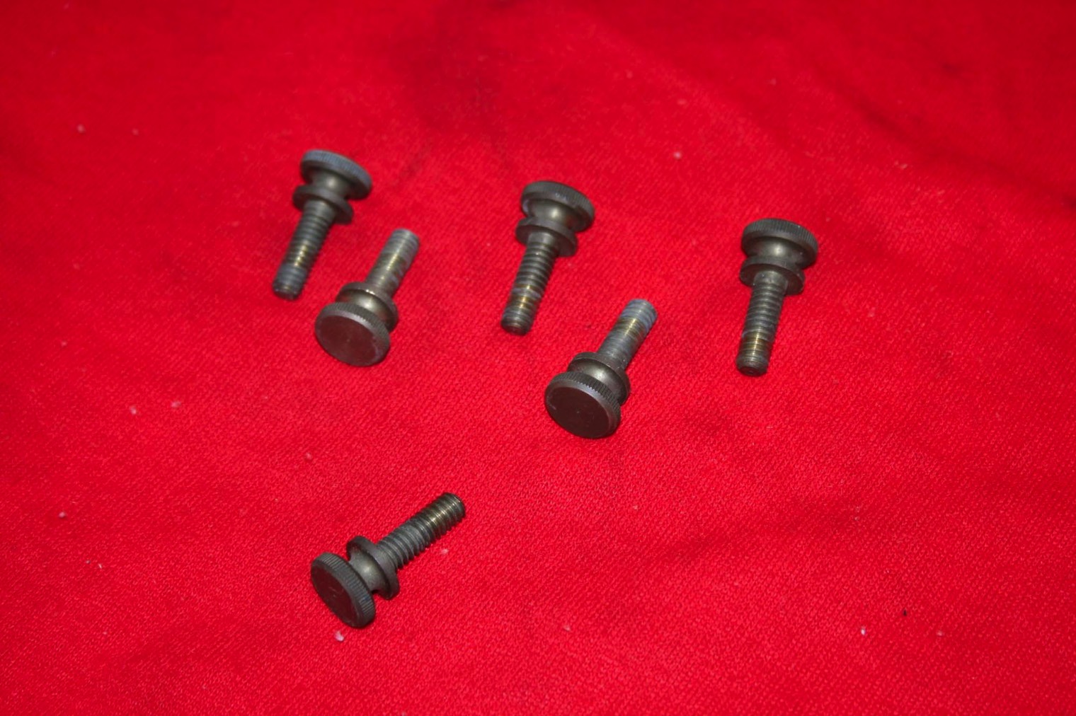
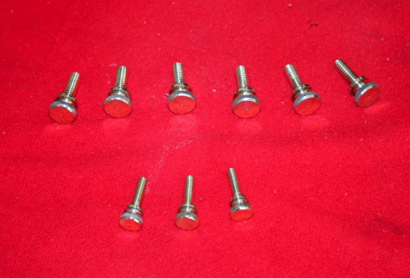
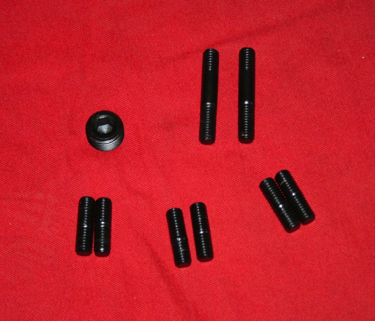
There are two studs in each pier leg that hold the leg to the pier. There are also two studs that thread into the bottom of each outer tube ring to mount the OTA in the saddle. These were a bit corroded so I bead blasted them and had them coated using a process called Kephos by Keco Coatings. It is a very durable yet thin finish. I also sent the cover plug that goes in the declination housing to allow access to the bolt that holds the housing to the RA shaft.
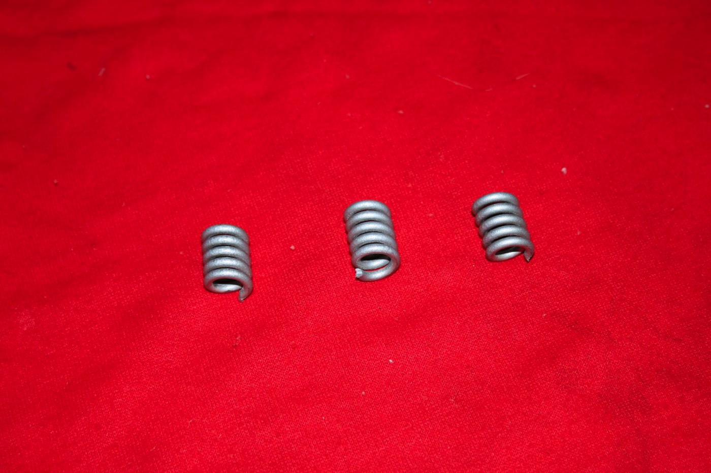
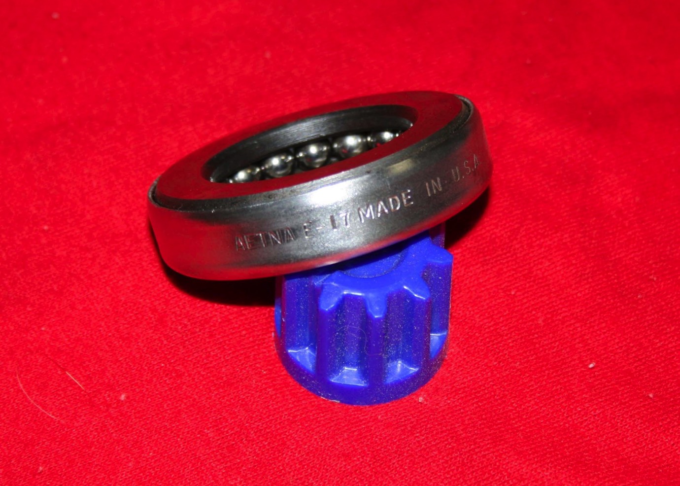
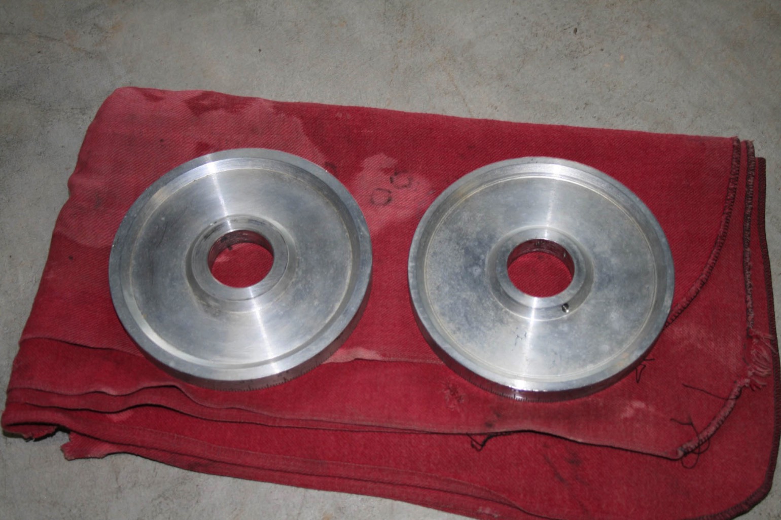
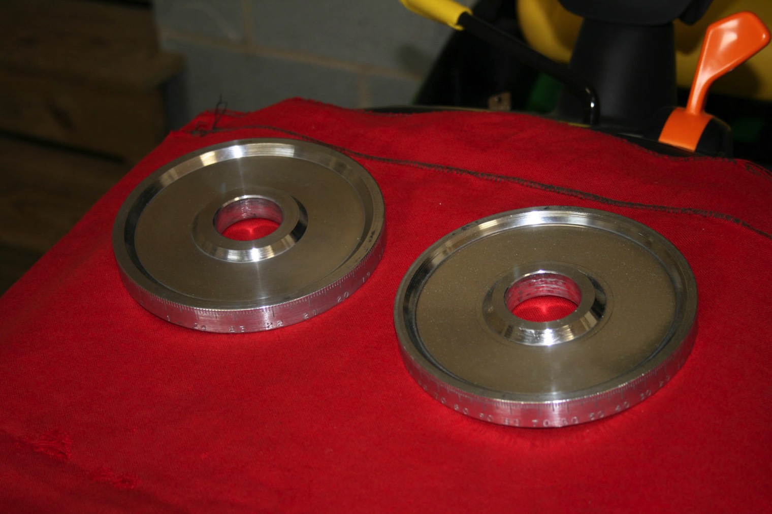
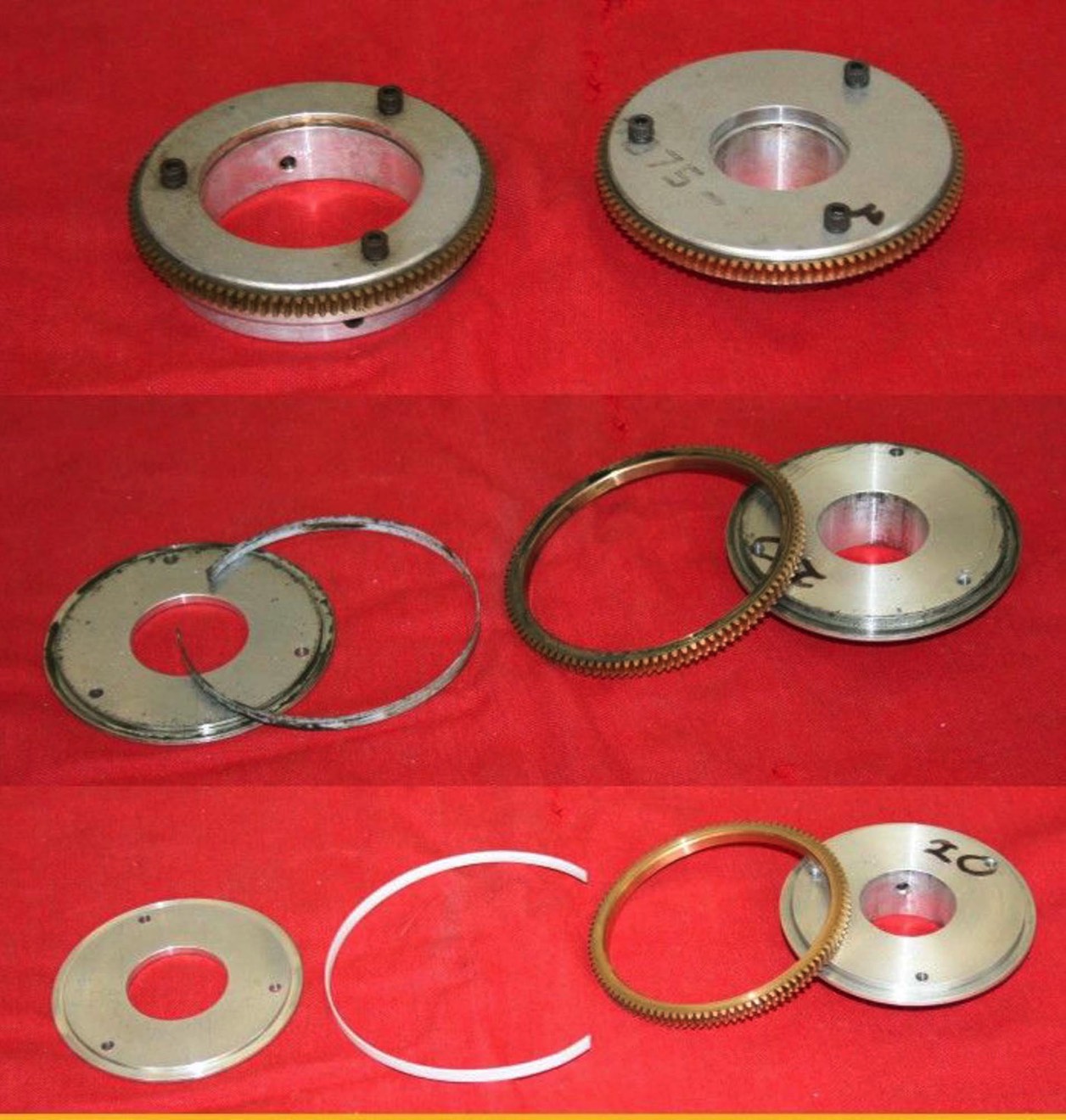
Time to rebuild the clutches. The 360 degree declination drive clutch is the one with the larger hole. Tension on both clutches is adjusted with the three socket head cap screws on the top which in turn compress each half of the clutch against the brass driven gear. A thin strip of Teflon material keeps the brass ring from rubbing on the inside of the hubs.
These were reassembled with a small amount of lithium grease on only the top and bottom surfaces of the ring gear.
These were reassembled with a small amount of lithium grease on only the top and bottom surfaces of the ring gear.
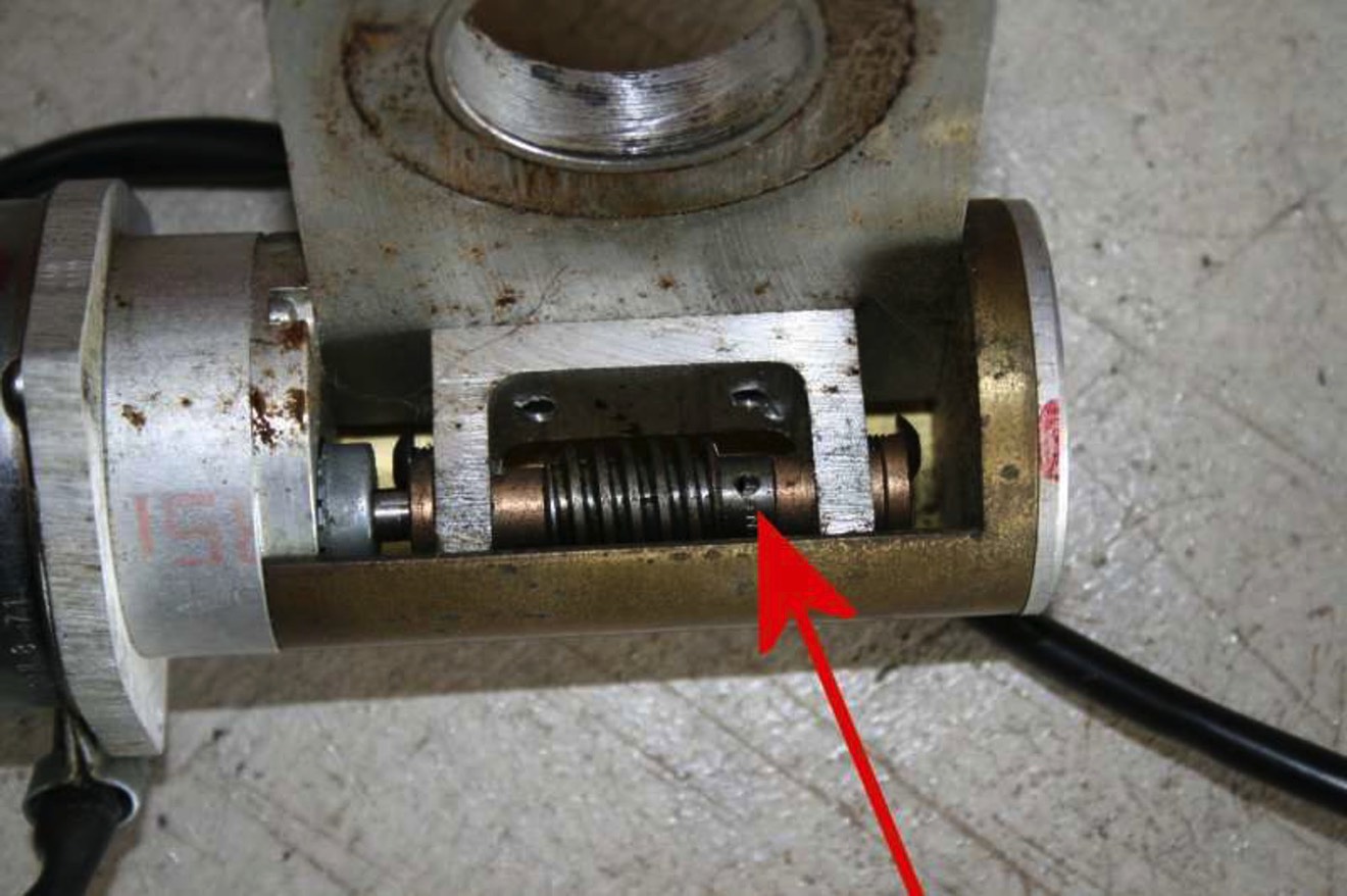
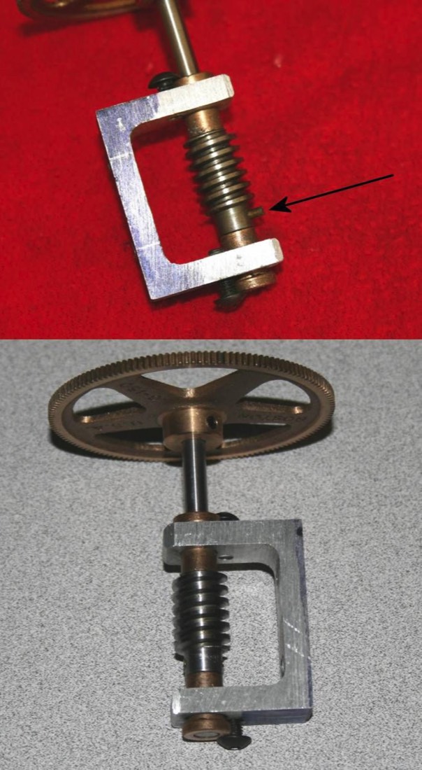
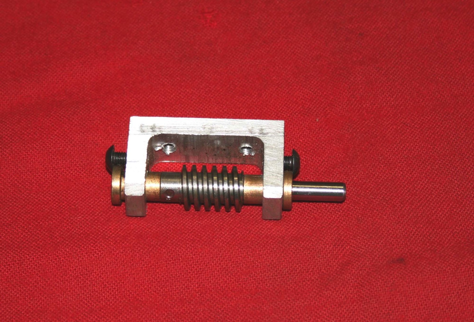
I didn’t need to disassemble the RA drive worm gear and support but I did find it was about to do the same thing the declination drive had done – shed its drive pin. I removed this pin and reinstalled it using purple Loctite 222 (low strength). I had thought about using red Loctite but this is really for assembling parts that won’t be taken back apart again. The 222 would still allow for later disassembly but should hold the pin in fine.
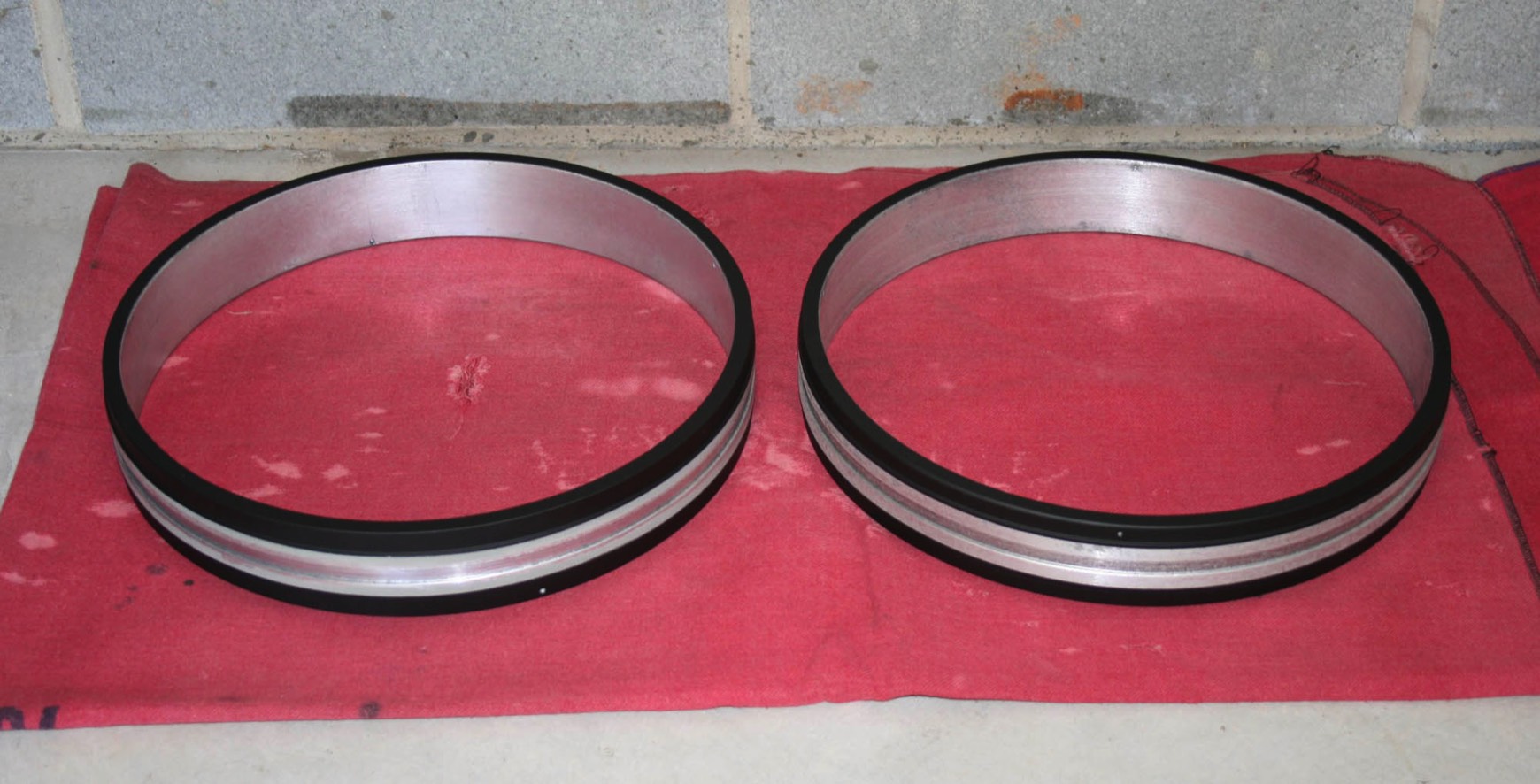
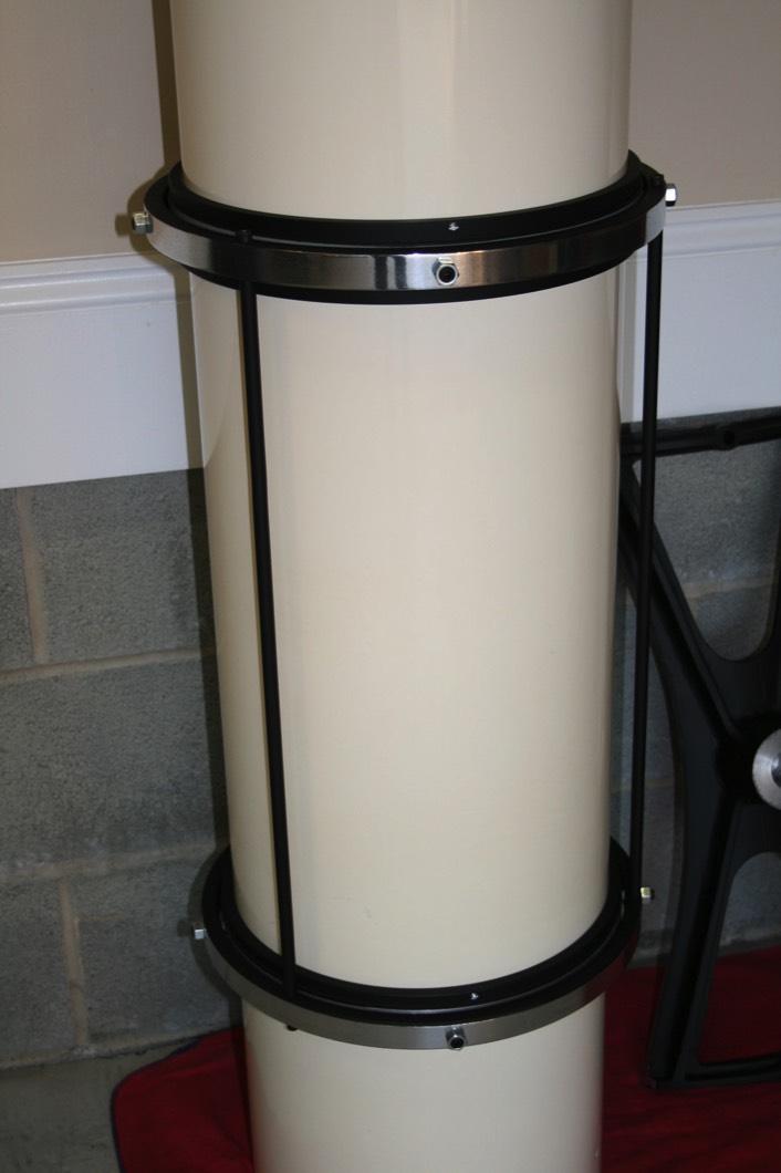
Next the inner tube rings were slid on from the bottom. Before sliding these on compare the locations of the 6-32 screws that go through the rings into the tube. Cave was not very precise in drilling these and they will probably fit only one way with the top and bottom also being different (you did mark them top and bottom when you took them off, right?).
Now you need to grease the groove in the inner tube rings. I use lithium grease. Just a thin coating is fine.
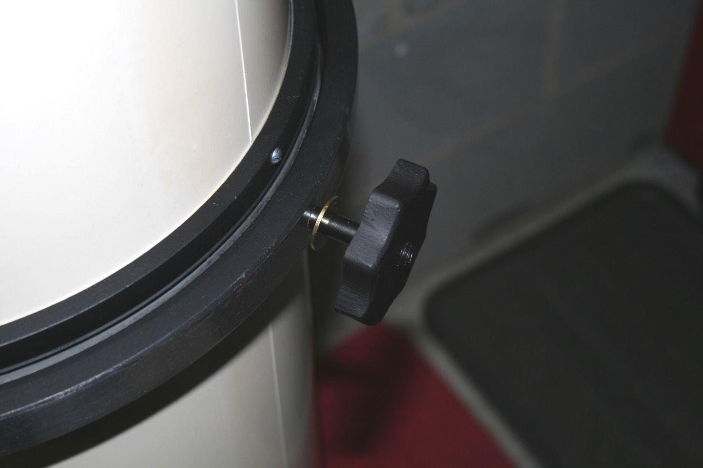
Next, slide the lower outer tube ring down and hold it over the groove in the inner ring. The OTA rides on four 5/16” diameter nylon slugs spaced around the ring. These slugs are in turn held in place and tensioned with 3/8” socket head set screws (on some models these are fine thread, others course thread). The set screws are locked in place with the outer nuts. A friend to hold the ring while you insert the slugs and set screws can be a big help here. Adjust the tension on the set screws until you have an even gap between the inner and outer ring all the way around and the outer ring spins smoothly.
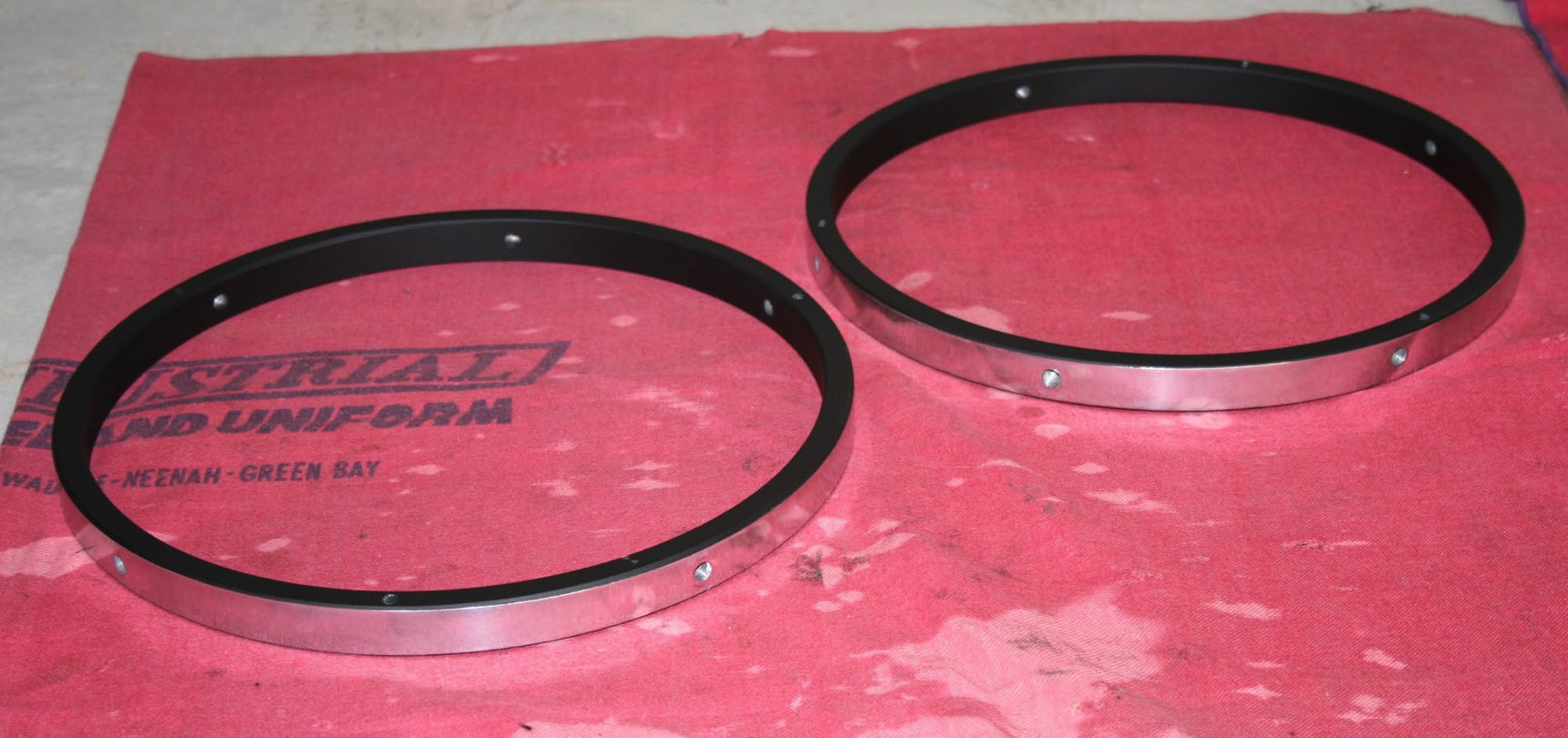
Then insert the outer ring spacer rods in the first ring. Finally, lower the other ring down the tube onto the spacer rods. Make sure the fifth hole on the outer rings, which is where the OTA mounting studs go, line up with each other along the axis of the tube. Repeat the procedure for installing the slugs, set screws and nuts. Install the nuts (or bolts on some models) on the ends of the spacer rods.
Next, slide the lower outer tube ring down and hold it over the groove in the inner ring. The OTA rides on four 5/16” diameter nylon slugs spaced around the ring. These slugs are in turn held in place and tensioned with 3/8” socket head set screws (on some models these are fine thread, others course thread). The set screws are locked in place with the outer nuts. A friend to hold the ring while you insert the slugs and set screws can be a big help here. Adjust the tension on the set screws until you have an even gap between the inner and outer ring all the way around and the outer ring spins smoothly.
Then insert the outer ring spacer rods in the first ring. Finally, lower the other ring down the tube onto the spacer rods. Make sure the fifth hole on the outer rings, which is where the OTA mounting studs go, line up with each other along the axis of the tube. Repeat the procedure for installing the slugs, set screws and nuts. Install the nuts (or bolts on some models) on the ends of the spacer rods.
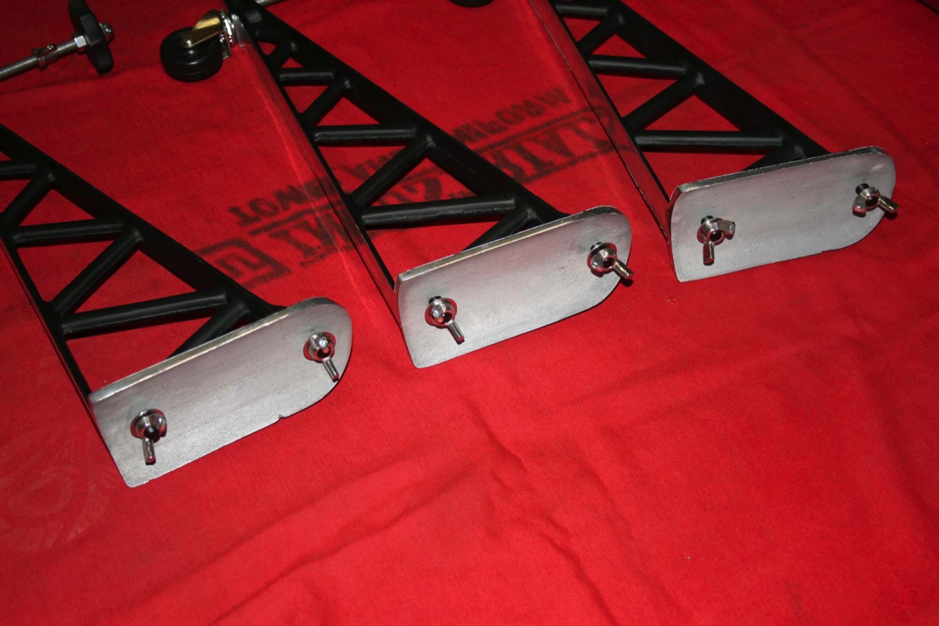
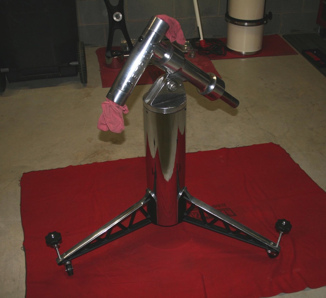
This picture shows the legs bolted to the pier. The pier cap is reinstalled with new ¼”-20 set screws. Then the RA shaft housing is bolted to the cap, a rough guess at the elevation angle is set and the set screw in the pier cap tightened. Next the declination shaft housing is bolted to the RA shaft with a socket head cap screw that goes through the access hole in the side of the declination shaft housing. Finally the hex plug is screwed into the declination shaft housing.
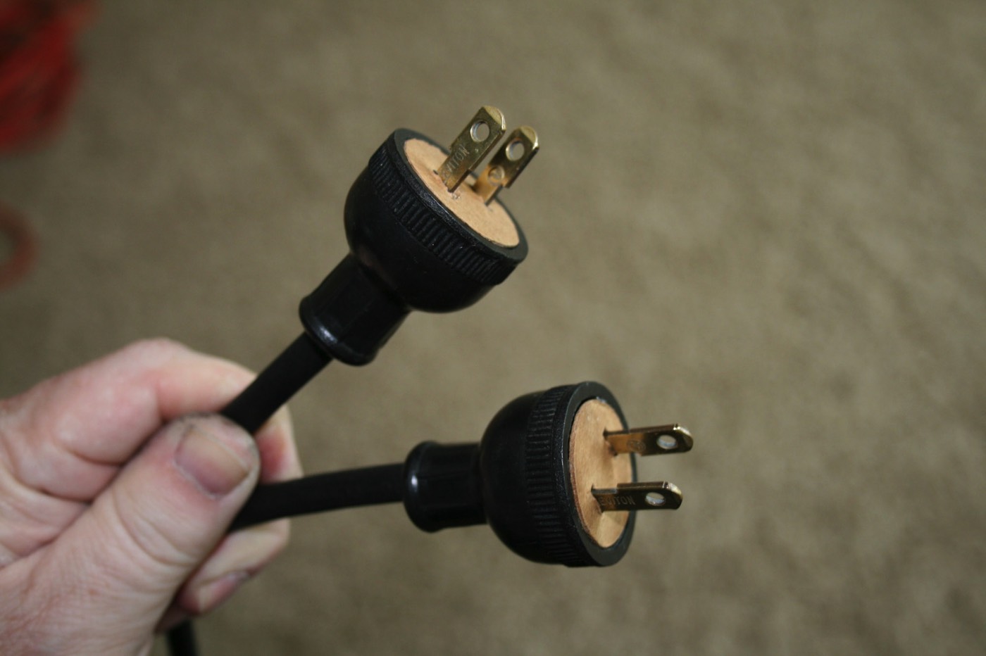
Now it is time to reassemble the drive electronics. The two AC cords were badly cracked from age and very dangerous. These are a two conductor cord with a ribbed outer jacket, much like you’d fine on a vacuum cleaner. I had an old florescent lamp that had the exact same cord as the originals so it sacrificed itself for the greater good.
I reused the original Leviton plugs. One was missing its cardboard disk so I made a duplicate from some thin cardboard. Of course I had to polish the brass prongs.
I reused the original Leviton plugs. One was missing its cardboard disk so I made a duplicate from some thin cardboard. Of course I had to polish the brass prongs.
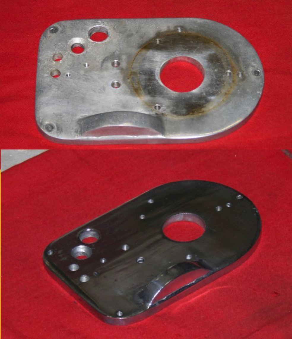
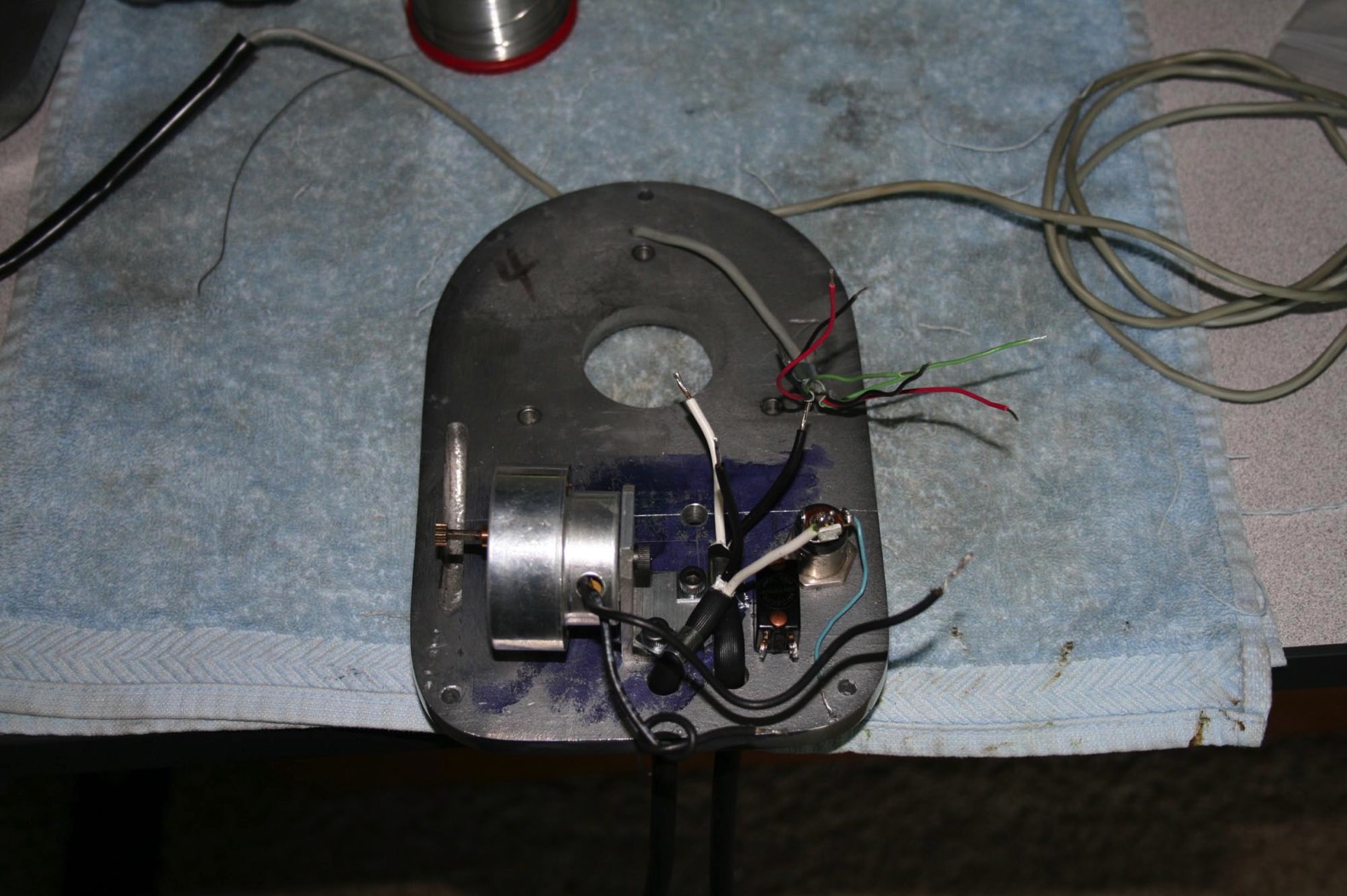
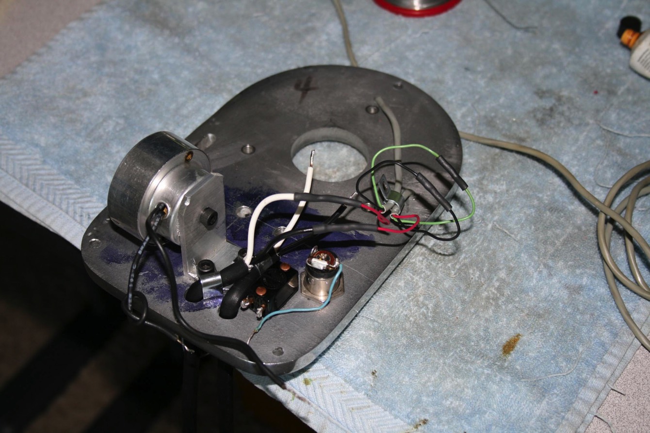
The next step was to mount all of the electrical components in the RA drive top plate. This shows the RA drive motor and its bracket back on. The motor mounting screw should be left loose at this point. The AC cords are held in with small clamps, which on mine went under the RA drive motor bracket mounting screws. I stripped about 2 inches of the outer jacket off of each AC cord. The toggle switch and lamp are also back in.
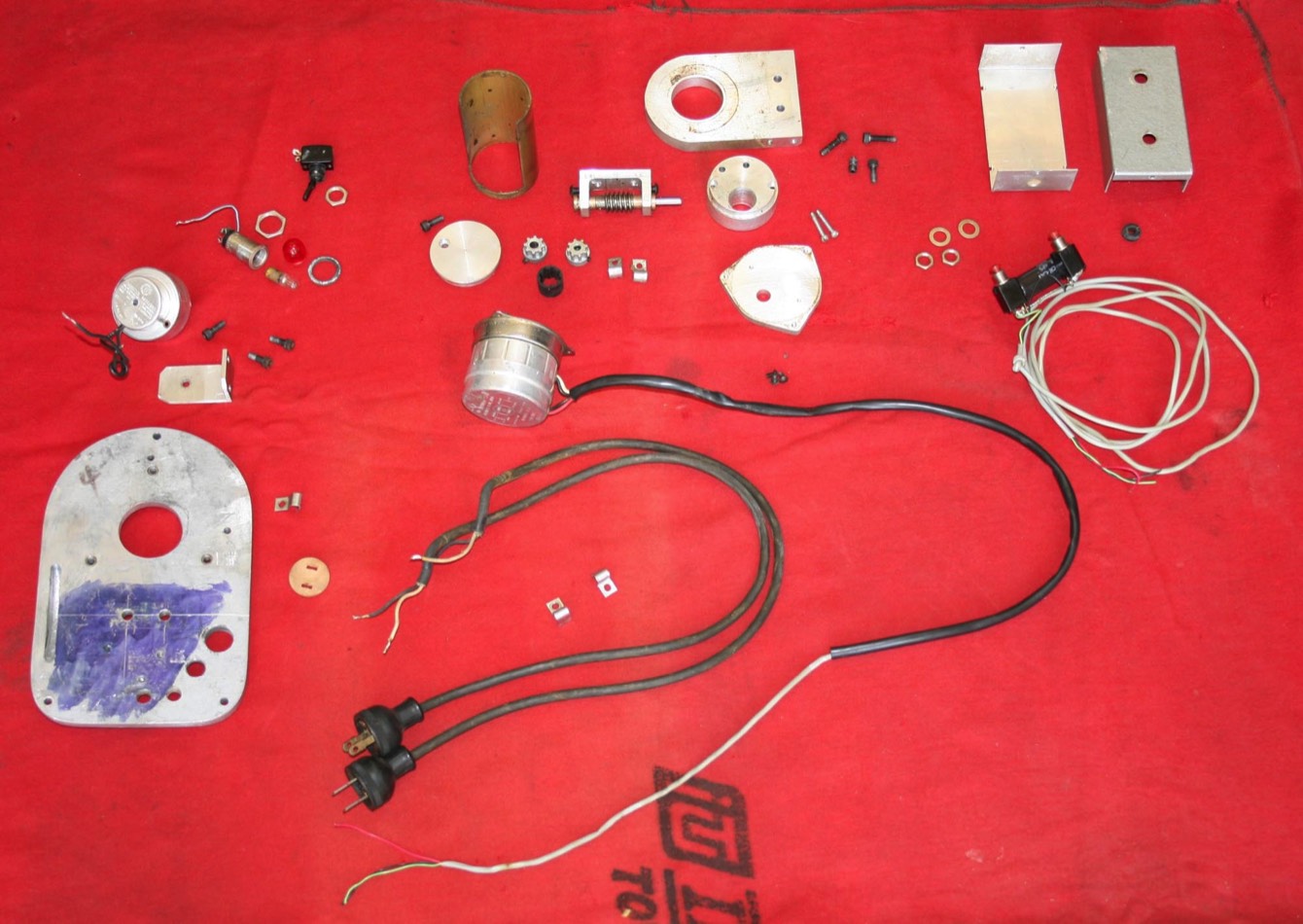
Then the cords for the declination drive motor and control box are fed through holes in the plate. Both will be held down with a single clamp that goes under one of the screws that will hold the plate to the bottom of the RA shaft housing. The grey cord at the top is for the declination drive motor while the one on the side is for the control box. Be sure to get the motor cord through the correct hole as shown as there are others in this area that are used to mount the plate and drive cover.
Then the cords for the declination drive motor and control box are fed through holes in the plate. Both will be held down with a single clamp that goes under one of the screws that will hold the plate to the bottom of the RA shaft housing. The grey cord at the top is for the declination drive motor while the one on the side is for the control box. Be sure to get the motor cord through the correct hole as shown as there are others in this area that are used to mount the plate and drive cover.
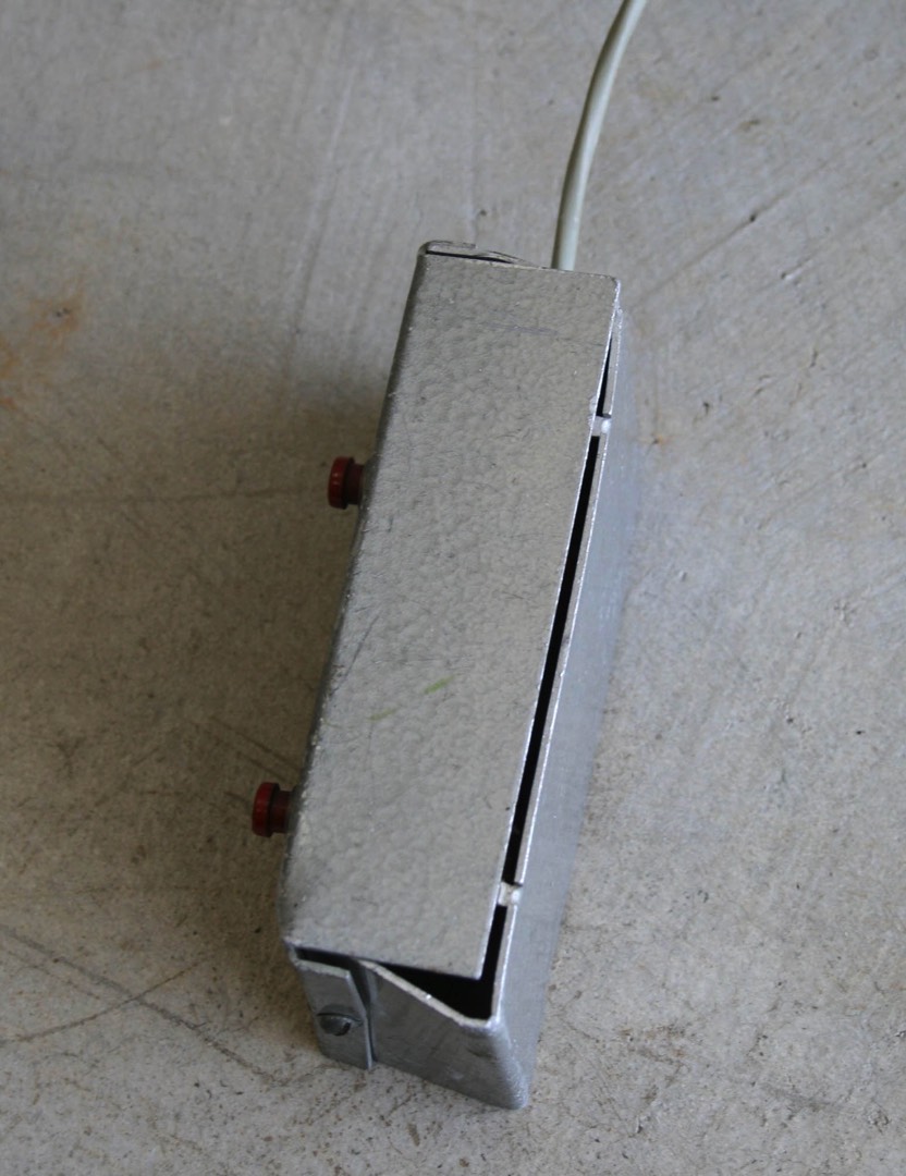
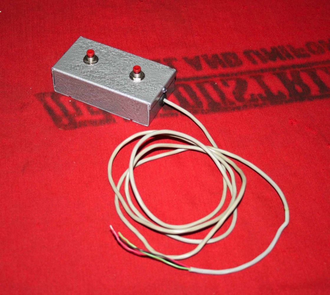
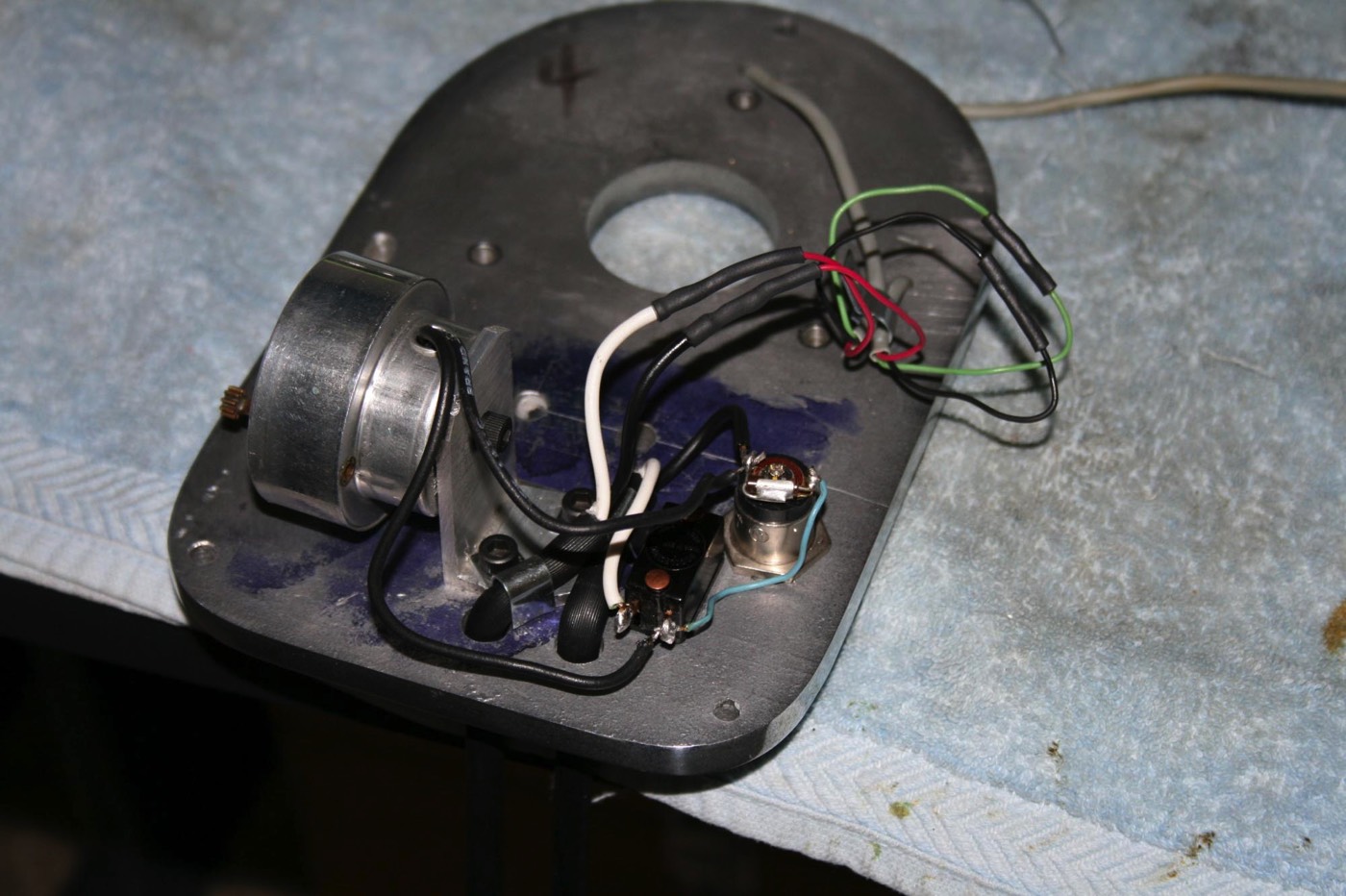
Then I wired up the declination drive control box. The green wire from the control box gets spliced to the green wire from the drive motor. The black wire from the control box gets spliced to the black wire from the drive motor. The white lead from the AC cord goes to the red wire from the control box and the black wire from the AC cord goes to the red wire from the drive motor. Each splice was soldered and covered with heat shrink tubing.
If you are curious why there is a red, white and two black wires going into the dec. drive motor but only a green, black and red wire coming out of the gray jacketed lead inside the drive housing - there are splices in the black covering that goes to the motor. Inside these are spliced – white from the motor to black in the grey lead, red from the motor to green in the grey lead and both blacks from the motor to red in the grey lead.
If you are curious why there is a red, white and two black wires going into the dec. drive motor but only a green, black and red wire coming out of the gray jacketed lead inside the drive housing - there are splices in the black covering that goes to the motor. Inside these are spliced – white from the motor to black in the grey lead, red from the motor to green in the grey lead and both blacks from the motor to red in the grey lead.
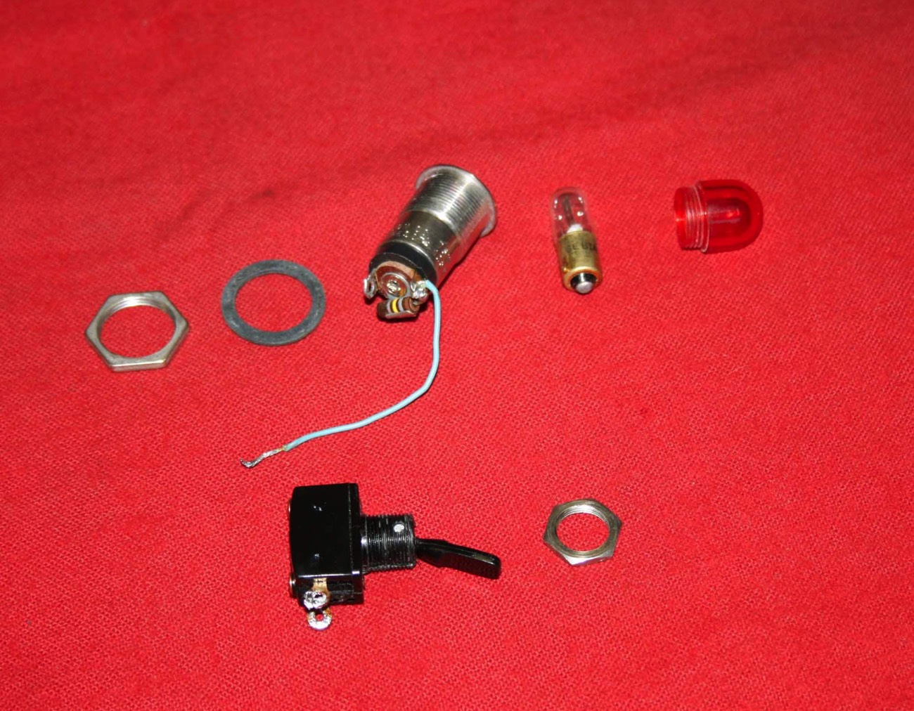
Next I wired up the clock drive. The black lead from the RA AC cord and one lead from the clock drive motor are soldered to the outer terminal on the lamp that does not also have the resistor connected to it. The resistor goes from the opposite outer terminal to the center terminal. The white lead from the RA AC cord goes to one side of the switch. The small blue wire, which is soldered on the side of the lamp with the resistor, goes to the other side of the switch along with the other clock drive motor lead. Normally I would cover the solder joints on the lamp and switch with pieces of heat shrink tubing to keep the wire from flexing and possibly cracking at the solder joints but Cave didn’t do this so I left them exposed.
Plug in and test.
Plug in and test.
Next is the RA drive worm and gear. This took some fiddling until I was happy with the lack of play between the worm gear and ring gear but could still turn the large driven gear easily. You also need to align the clutch so that its ring gear is centered on the drive worm gear. All gears are lubed with lithium grease.
Then I turned the clock drive motor until its gear engaged the driven gear. At this point I also fiddled with the three screws on the clutch. Even though the rest of the mount and scope were not on I got it where I felt it had enough tension to stay put but could still manually adjust the scope position without too much effort. It doesn’t take much of a turn on these screws to change the tension a lot.
Then I turned the clock drive motor until its gear engaged the driven gear. At this point I also fiddled with the three screws on the clutch. Even though the rest of the mount and scope were not on I got it where I felt it had enough tension to stay put but could still manually adjust the scope position without too much effort. It doesn’t take much of a turn on these screws to change the tension a lot.
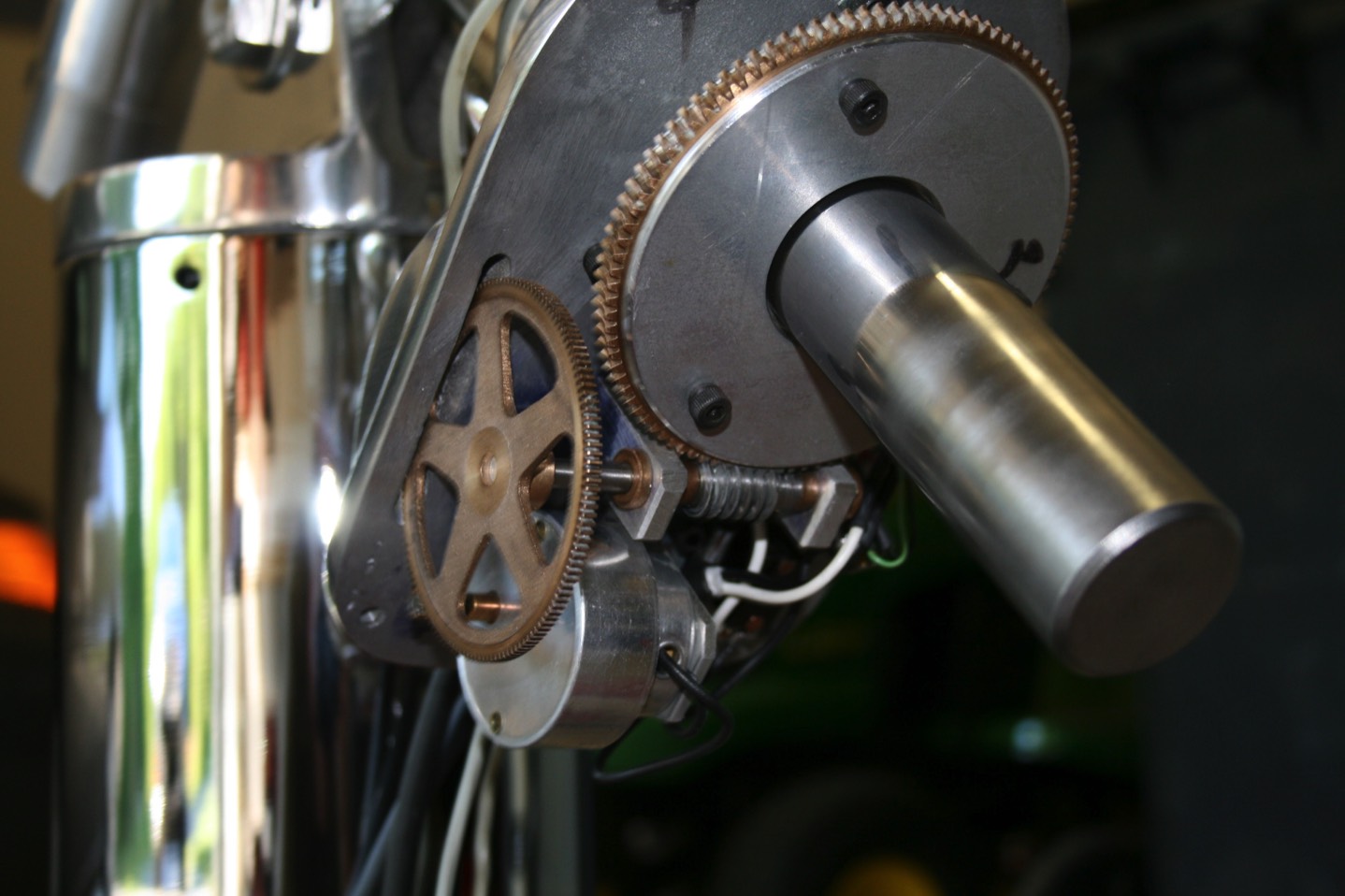
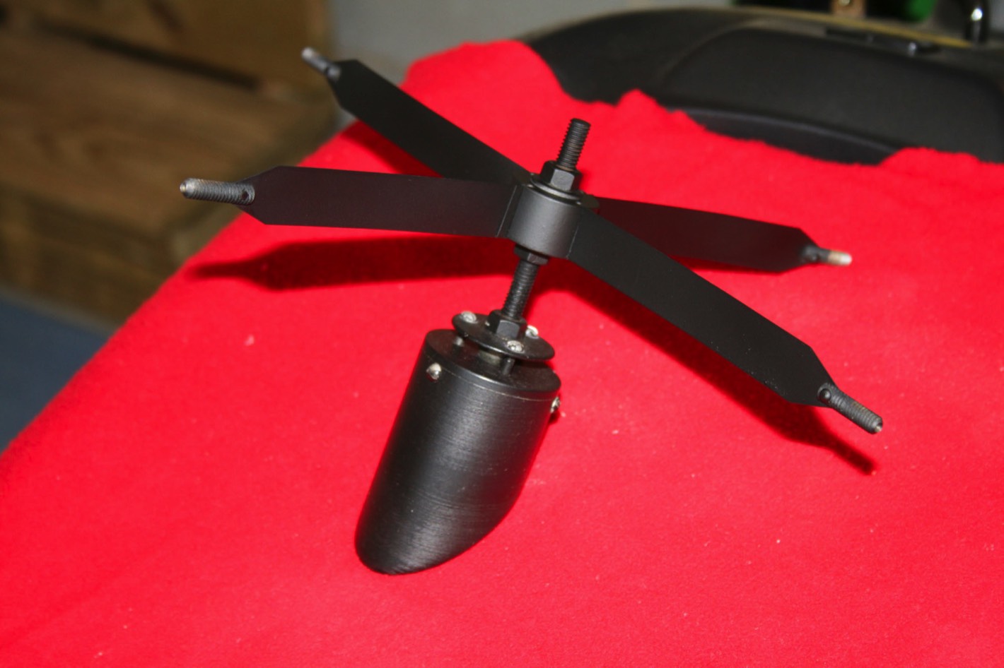
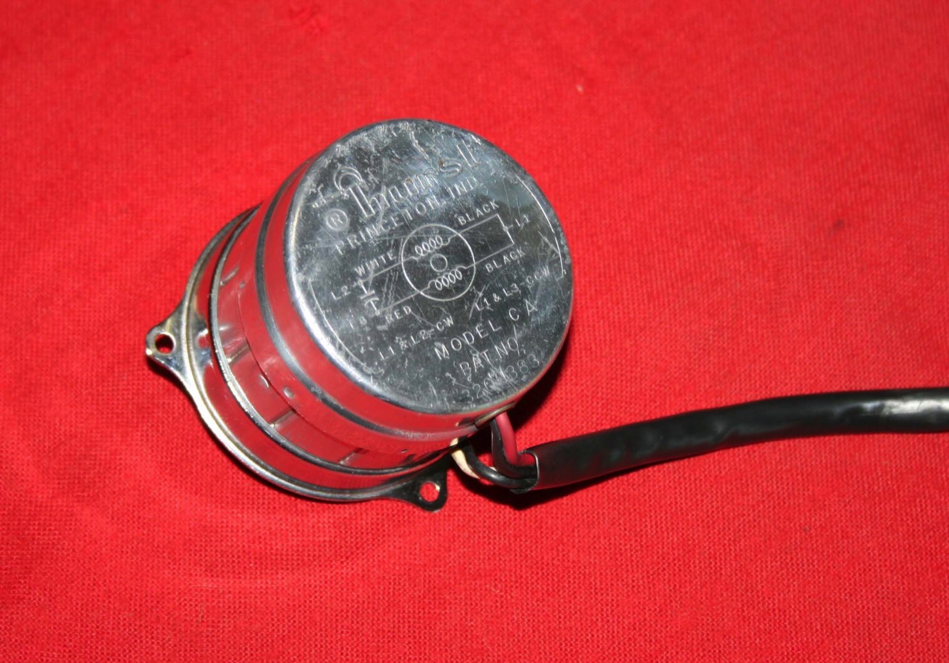
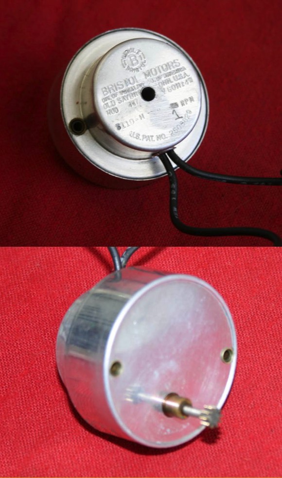
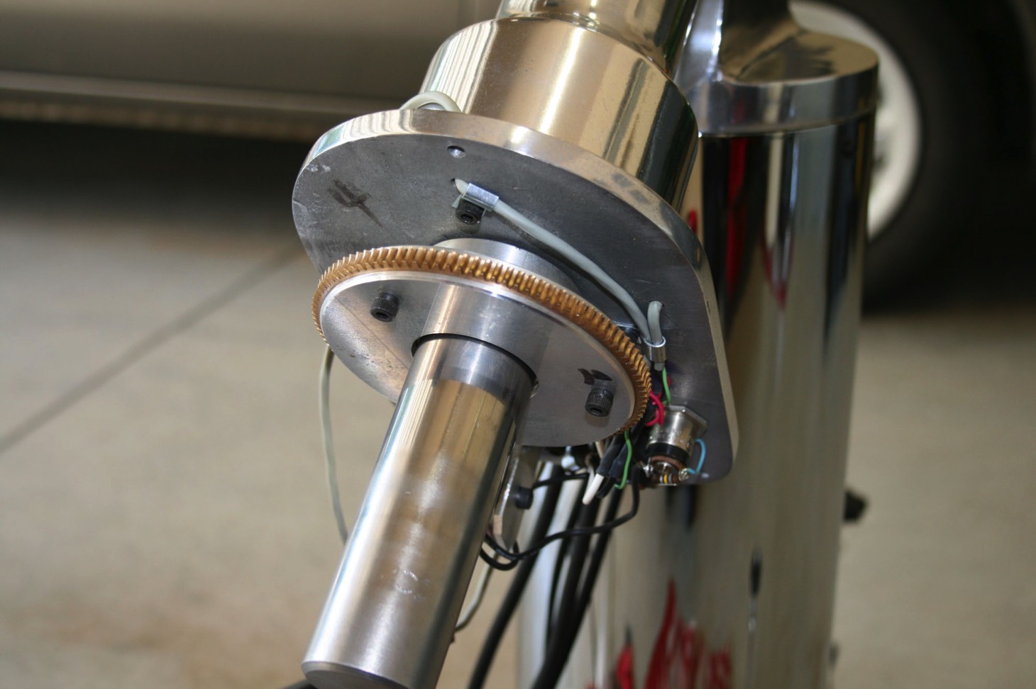
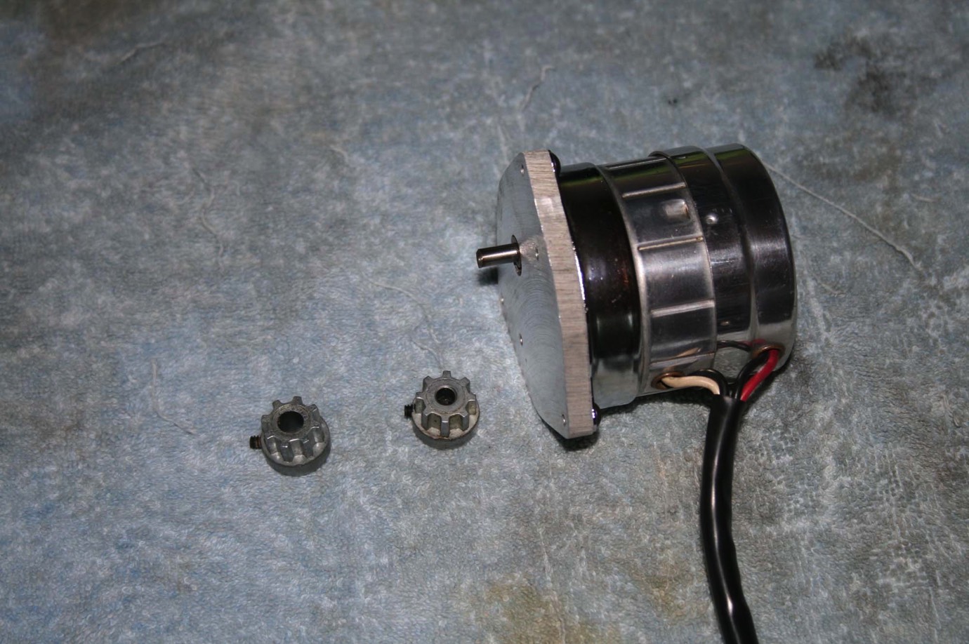
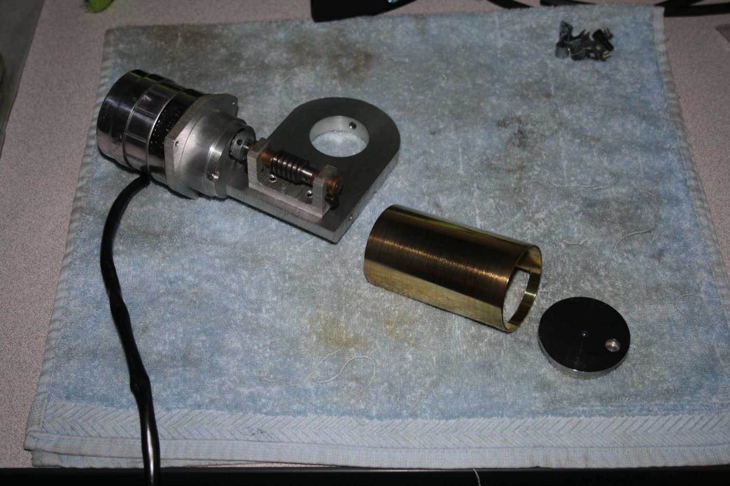
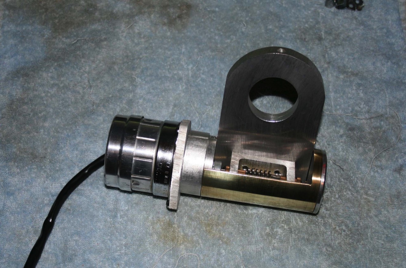
Moving to the declination side of things it’s time to reassemble the declination drive. This picture shows the motor and the two drive coupling gears.
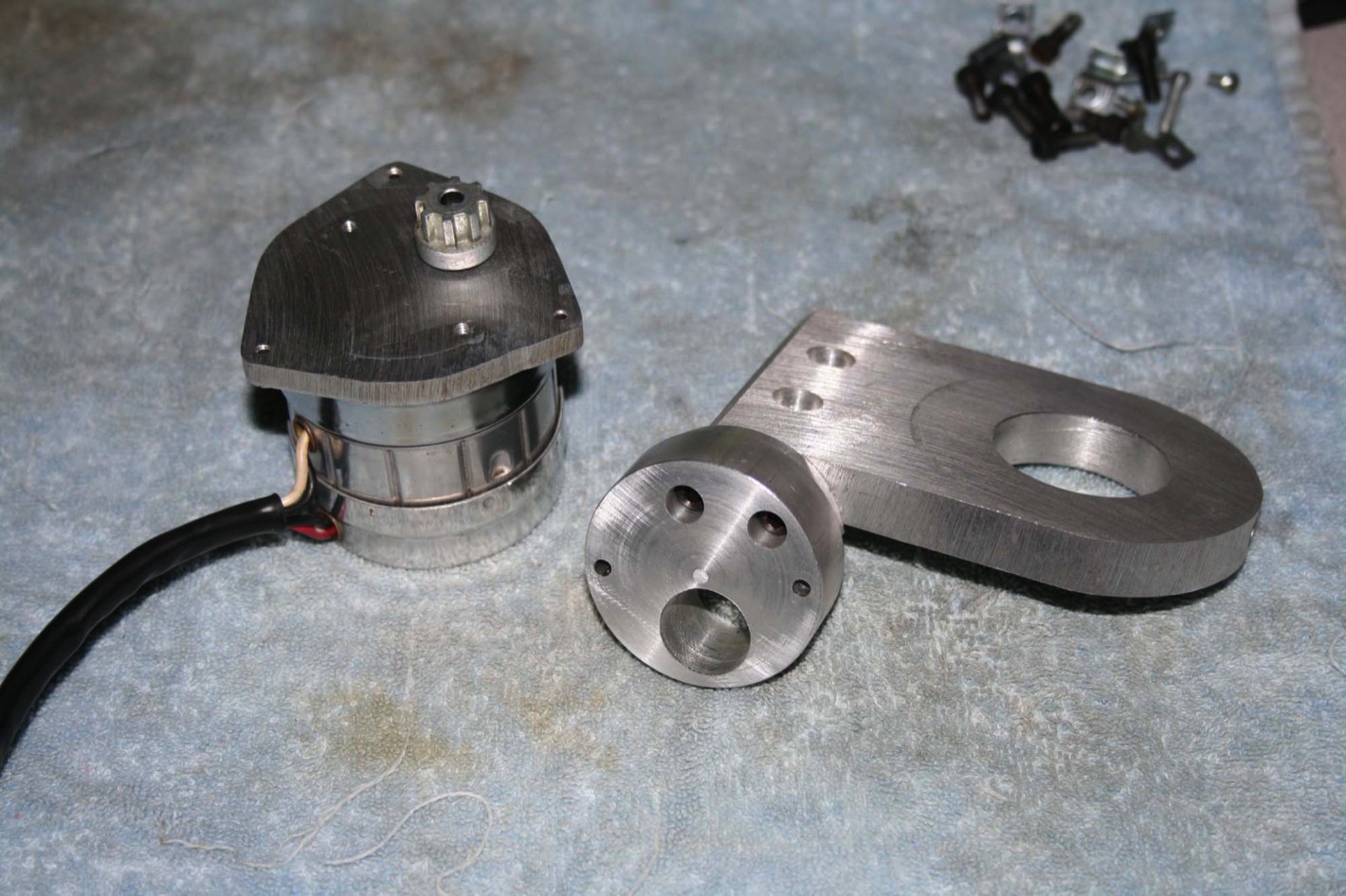
First the triangular adapter plate is screwed to the motor. There are two drive hubs that have an internal toothed rubber sleeve that connect them together. The hub with the smaller hole goes on the motor.
First the triangular adapter plate is screwed to the motor. There are two drive hubs that have an internal toothed rubber sleeve that connect them together. The hub with the smaller hole goes on the motor.
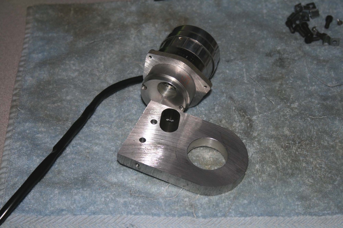
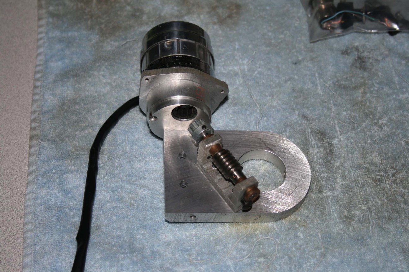
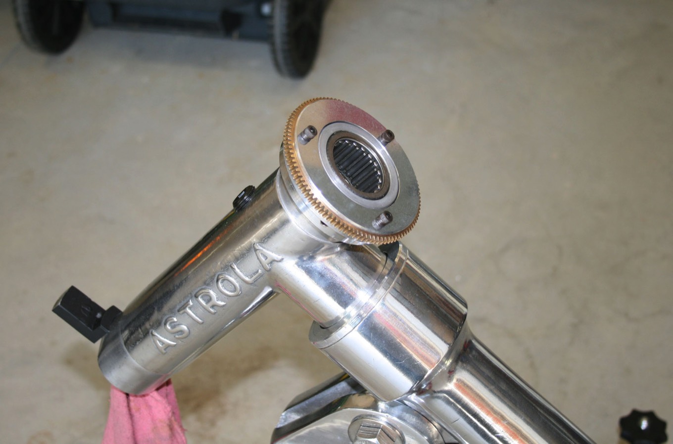
Next are the declination shaft, cradle support bearing, declination drive and cradle. I think on most Cave mounts you could bolt the cradle to the shaft and slide it down through the declination drive, bearing and declination housing from the top. But on this, with the lower 12” of the shaft being chrome plated, the plating is too thick to go through the bearings. So it was a bit of a trick to slide it up from the bottom and hold it while sliding on the bearing, declination drive and cradle from the top and getting the bolt into the cradle. As with disassembly, a friend helping here is a good idea.
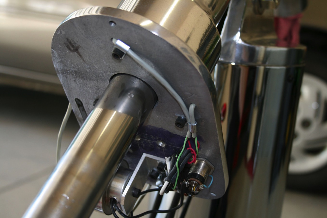
There is a set screw in the declination drive mounting plate that holds it to the declination shaft.
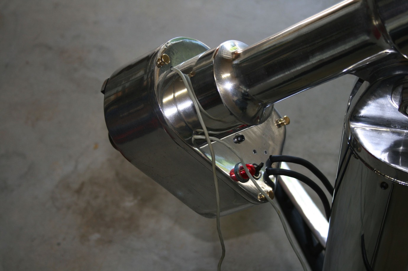
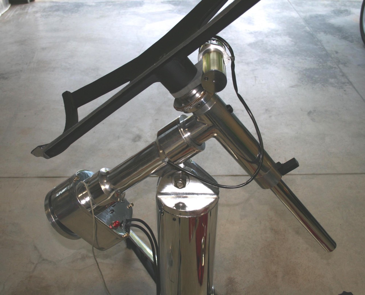
Here you can also see the lead for the declination drive motor run along the RA shaft housing and held on with two small clips and screws.
There is a set screw in the declination drive mounting plate that holds it to the declination shaft.
Here you can also see the lead for the declination drive motor run along the RA shaft housing and held on with two small clips and screws.
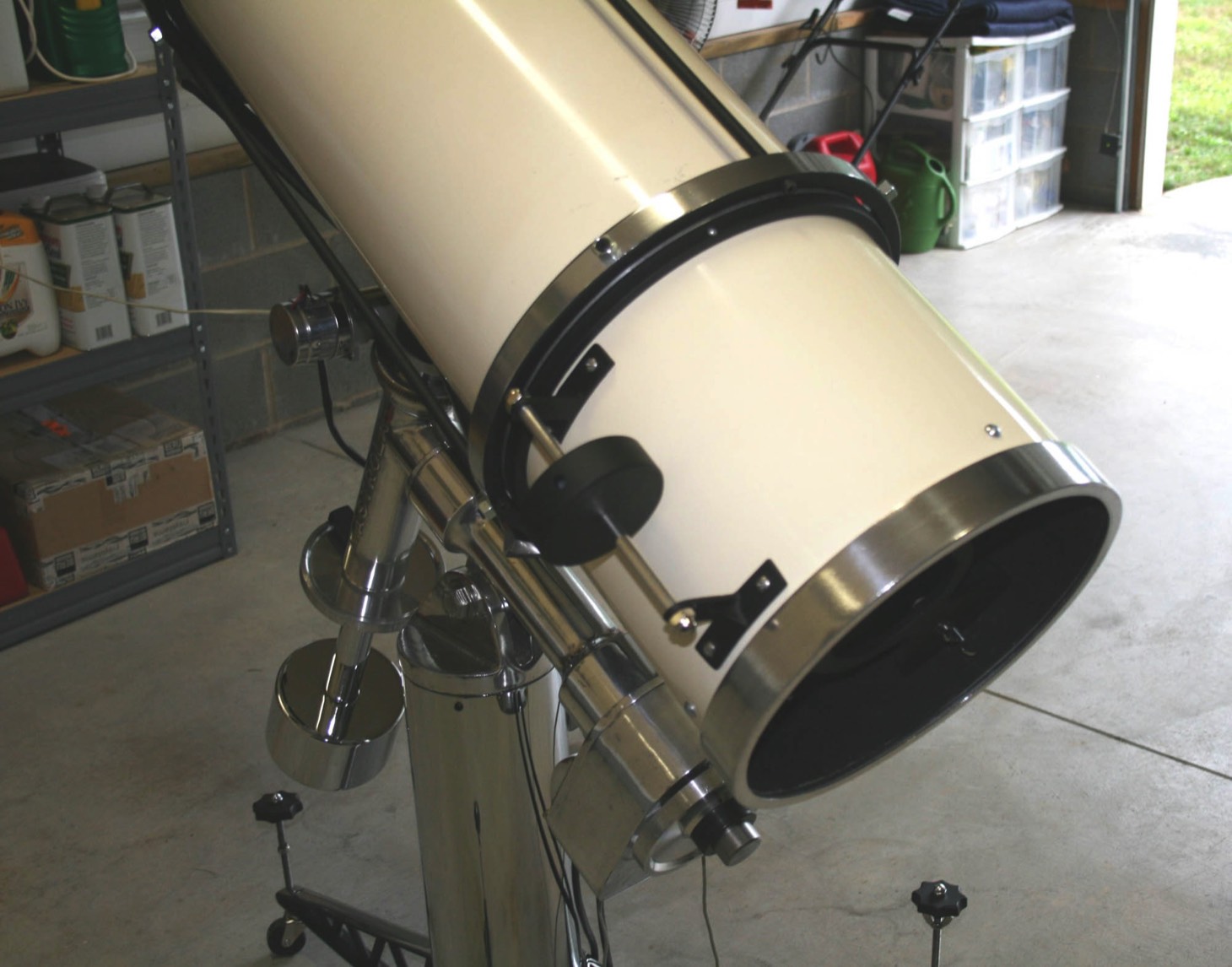
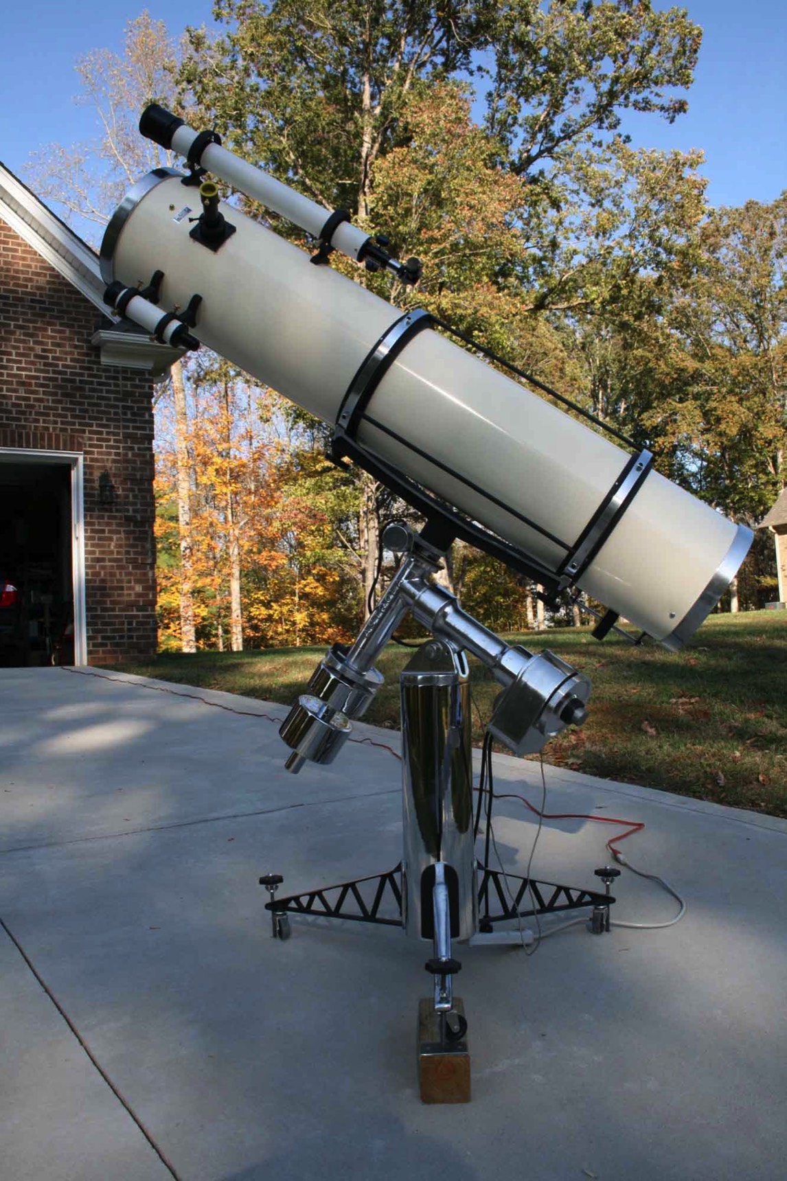
After the Cave was restored I decided I wanted to add the pieces that were supposed to come on a Custom Super Deluxe but were never delivered on this scope.
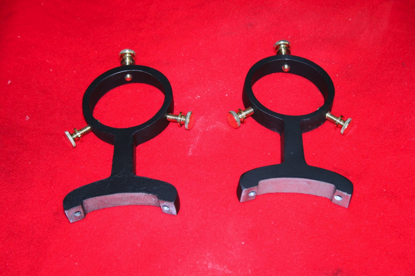
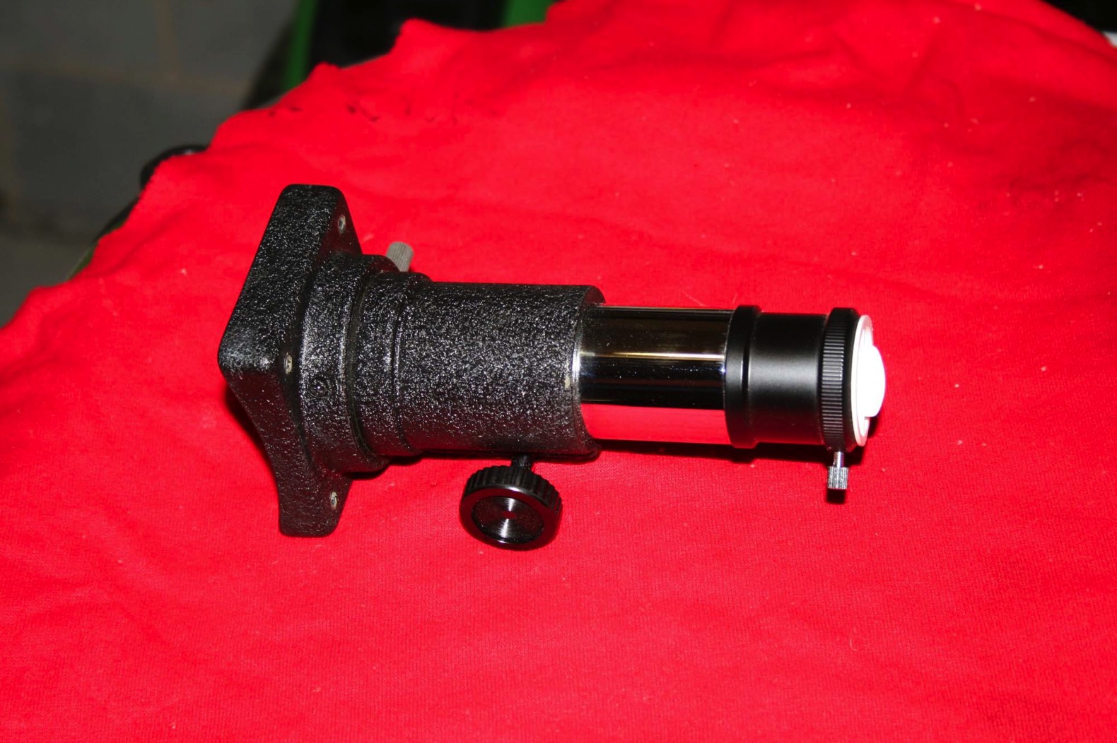
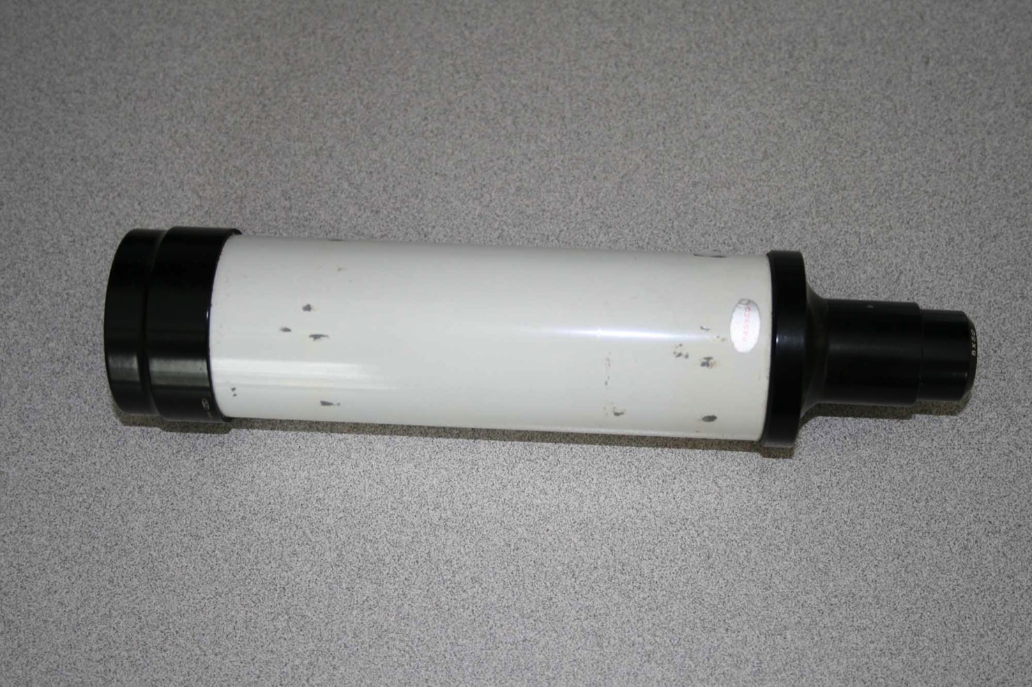
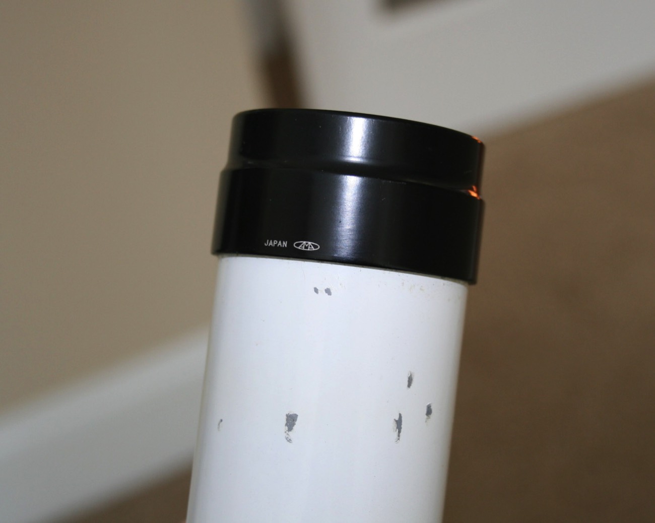
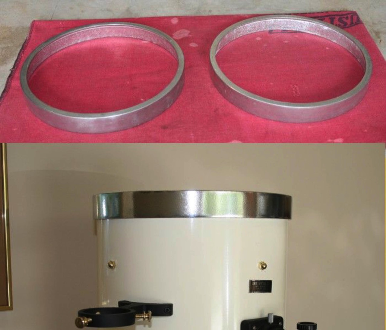
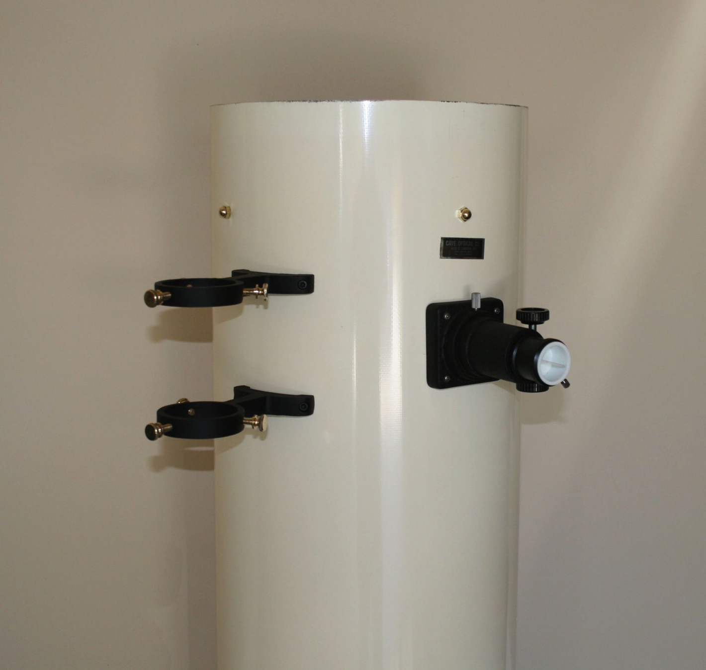
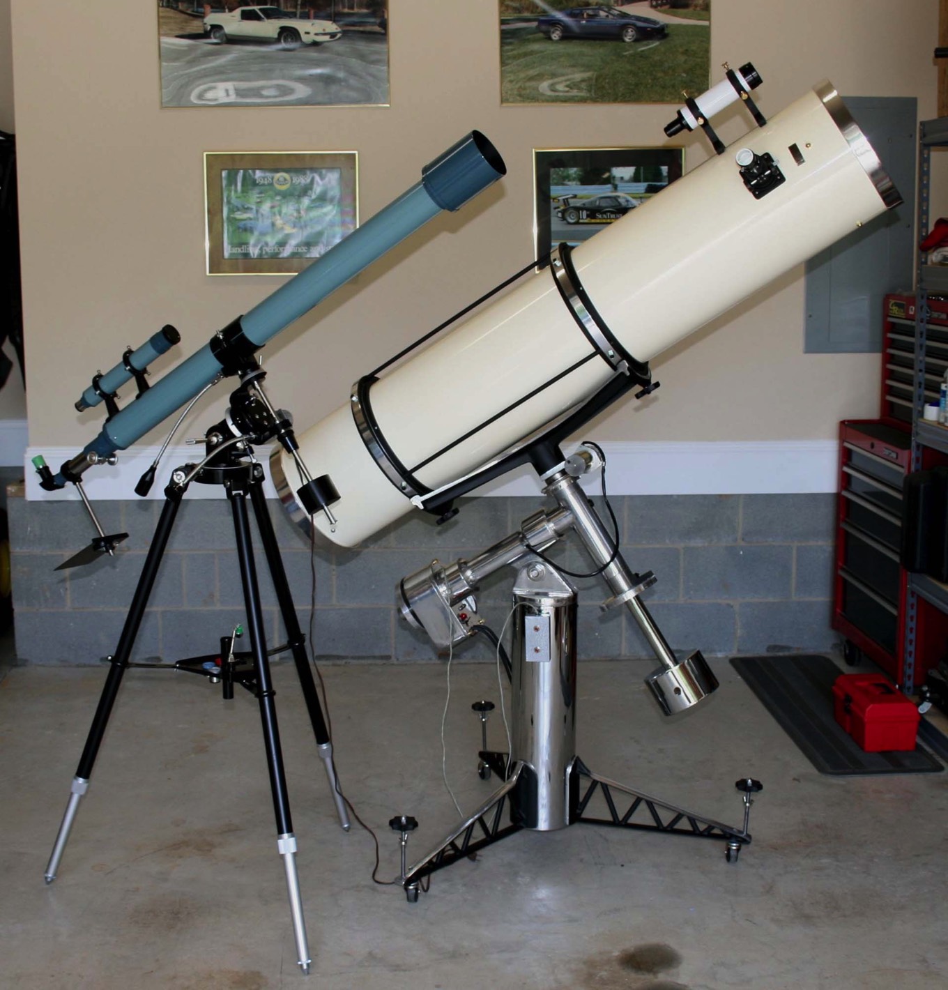
First up was the 2.4” guide scope. Thanks to two Cloudy Nights members for selling me a Towa manufactured 60mm x 700mm guide scope and Cave guide scope rings, my Cave now has a guide scope like it should have come with in 1971.
I was able to balance it around the polar axis by dropping the main counter weight about as far down as I can. It is now a bit nose heavy around the declination axis so I still needed to find a Cave tube weight.
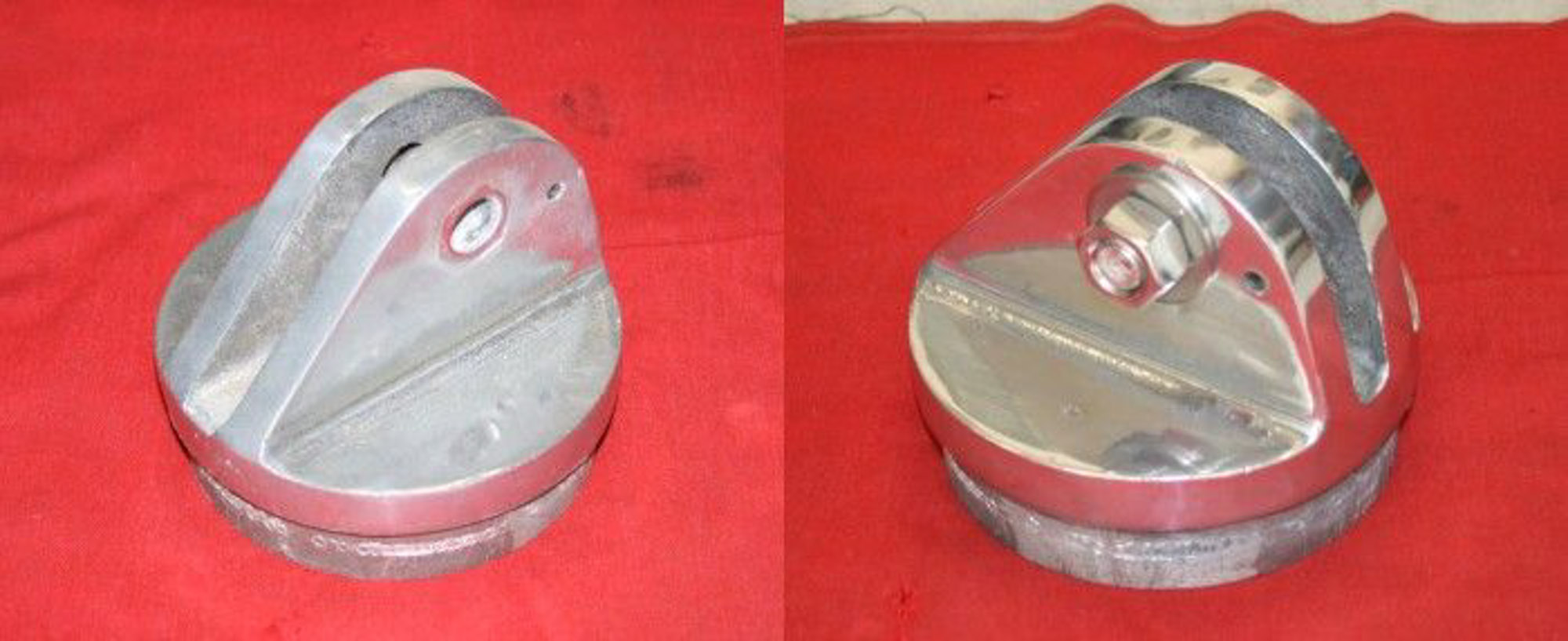
Thanks to another Cloudy Nights member I was able to add a tube weight setup.
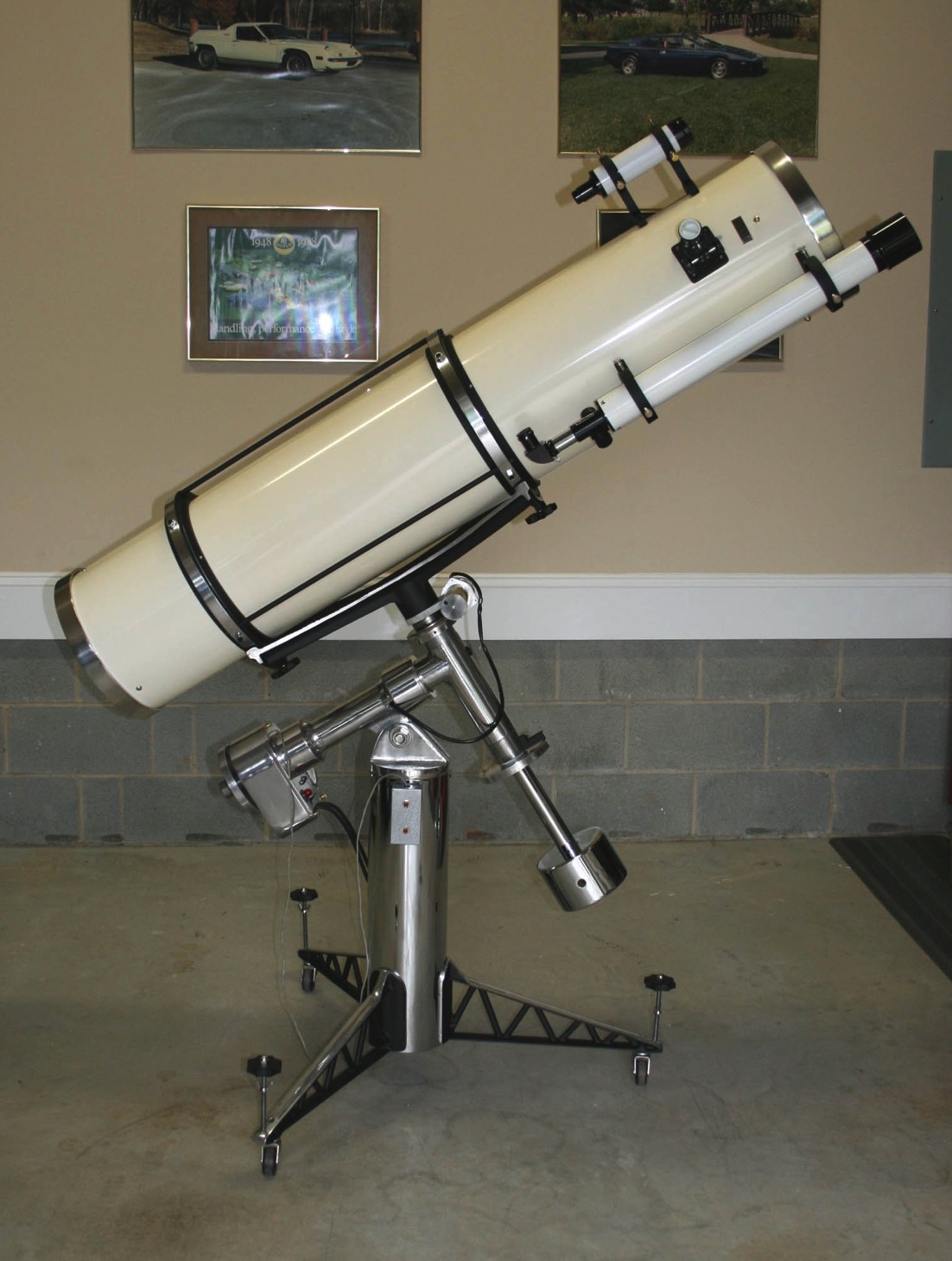
Before adding the guide scope, the OTA was already a tiny bit nose heavy but not enough where the clutches wouldn't hold it. But with the guide scope it was obviously going to be too nose heavy. And, as one CN member had warned me, the guide scope would want to seek bottom and slowly rotate the OTA. This is exactly what happened. I could have probably tightened up the rotating ring adjusters but this would only solve one of the problems and would just wear out the nylon pegs at the ends of the adjusters that ride in the groove of the inner ring.
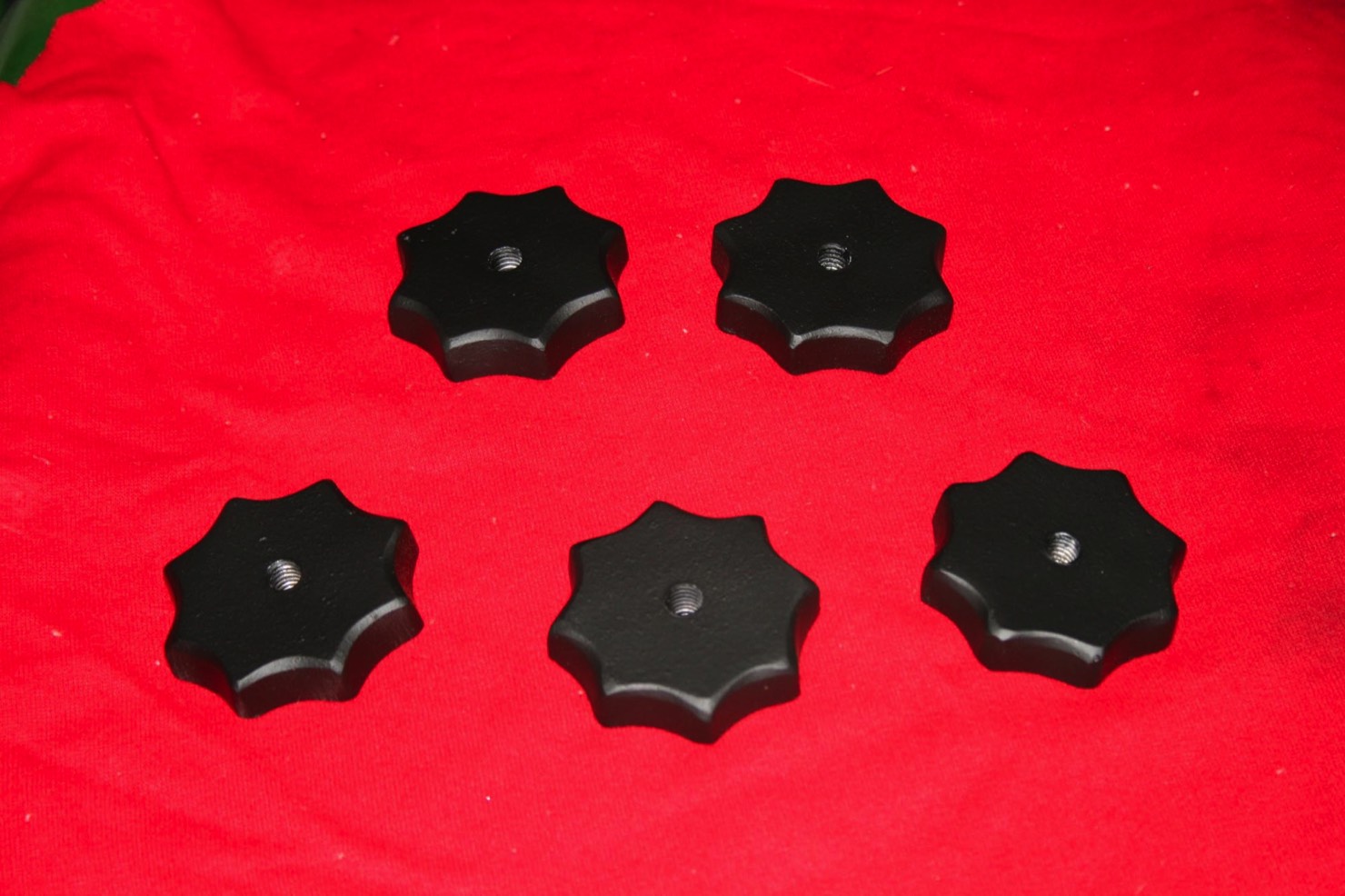
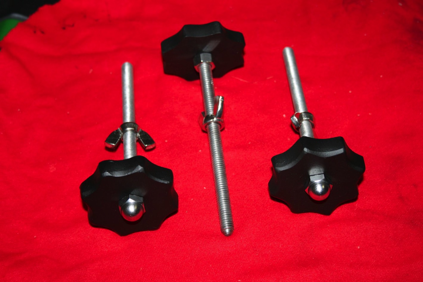
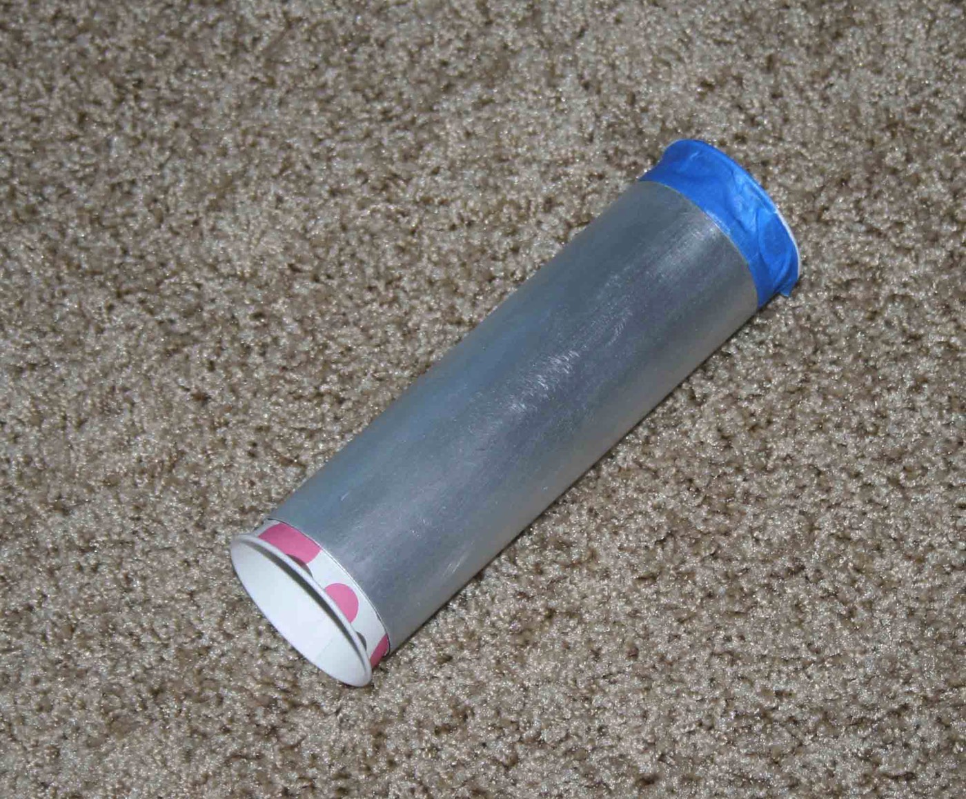
The rod that came with the mounts and weights was too long and marred up with lots of set screw marks so I made a new one to the right length and polished it and refinished the mounts and weights.
Now, where to place it? It obviously needed to go on the bottom end. There isn't much room between the lower rotating ring and the end of the tube so not much to think about there other than influencing the length of the new rod. To keep the guide scope from rotating the OTA the tube weight needs to be pretty much 180 degrees opposite of the guide scope. Of course this was pretty close to where one of the three legs of the mirror cell mount to the tube. So I did a slight bias toward being 180 degrees opposite of the focuser.
With a single 3 lb. weight in the middle of the rod the OTA axis is balanced perfectly. It is also perfect around the dec axis. But.....now we need more main counterweight.
Before adding the guide scope, the OTA was already a tiny bit nose heavy but not enough where the clutches wouldn't hold it. But with the guide scope it was obviously going to be too nose heavy. And, as one CN member had warned me, the guide scope would want to seek bottom and slowly rotate the OTA. This is exactly what happened. I could have probably tightened up the rotating ring adjusters but this would only solve one of the problems and would just wear out the nylon pegs at the ends of the adjusters that ride in the groove of the inner ring.
The rod that came with the mounts and weights was too long and marred up with lots of set screw marks so I made a new one to the right length and polished it and refinished the mounts and weights.
Now, where to place it? It obviously needed to go on the bottom end. There isn't much room between the lower rotating ring and the end of the tube so not much to think about there other than influencing the length of the new rod. To keep the guide scope from rotating the OTA the tube weight needs to be pretty much 180 degrees opposite of the guide scope. Of course this was pretty close to where one of the three legs of the mirror cell mount to the tube. So I did a slight bias toward being 180 degrees opposite of the focuser.
With a single 3 lb. weight in the middle of the rod the OTA axis is balanced perfectly. It is also perfect around the dec axis. But.....now we need more main counterweight.
I was soon able to find an original 20 lb. Cave weight. It turned out it was chrome plated (well, what little chrome was left). It was from a 10" Cave Cassegrain that had its mount accidentally removed out of the owner's garage during a charity donation (OTA and weight were off the mount at the time) and was lost.
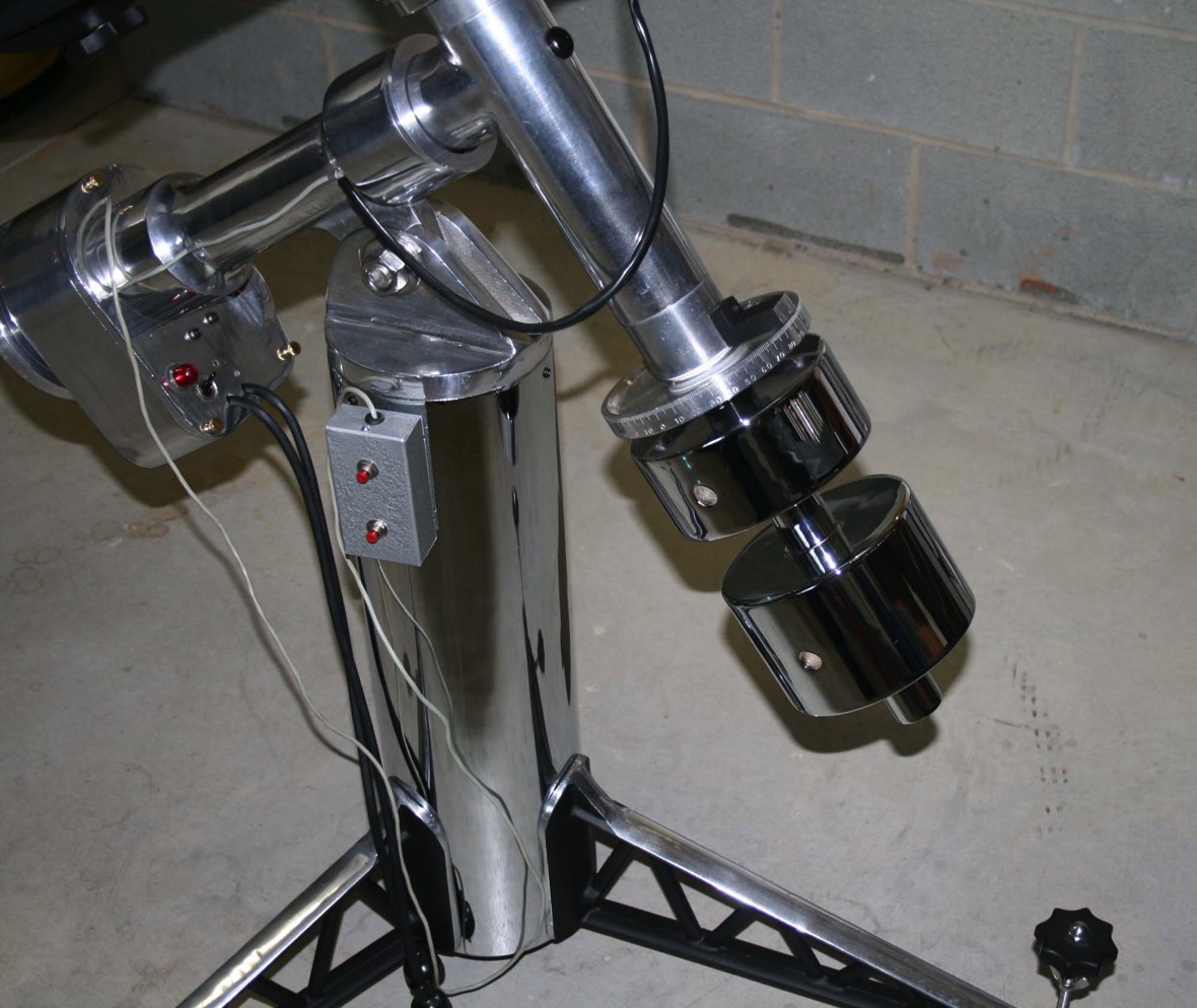
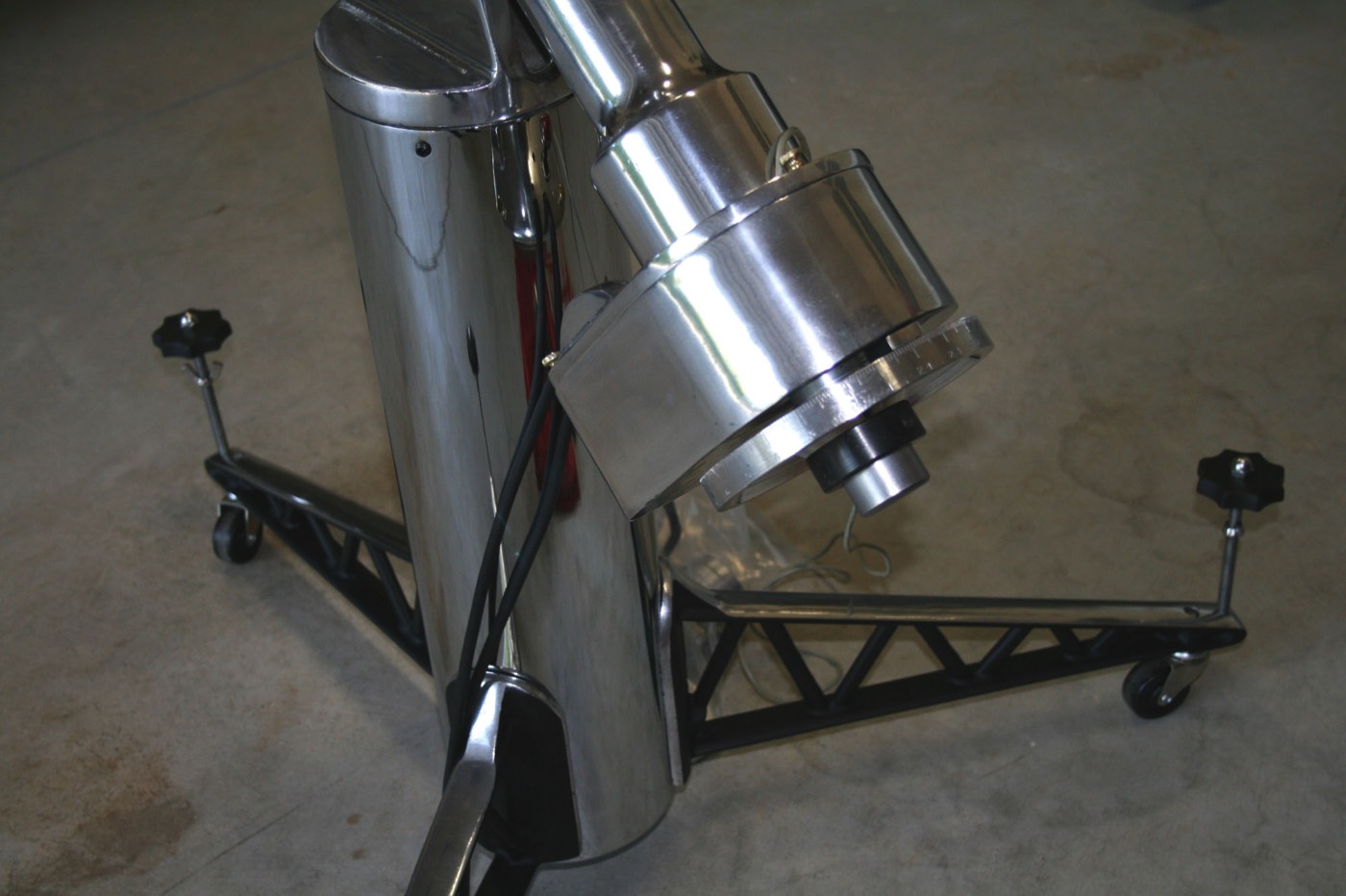
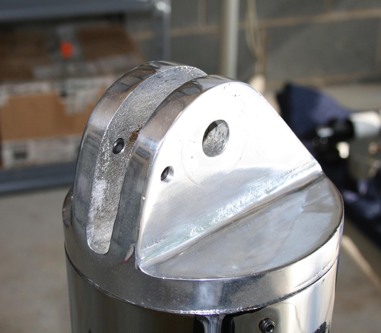
Another issue that came up was a bit of a safety issue. I found, with the extra weight that has been added, that I could not get the mount to hold its elevation setting firmly. It would slip when moving the scope, throwing the polar alignment off. The large bolt at the pivot point does not actually clamp the pier cap to the RA shaft housing. The whole thing was kept from pivoting by the one original ¼”-20 set screw in the pier cap, and the thing was only 3 threads long.
I don’t like removing metal or drilling holes in a classic scope but this called for a positive yet fairly invisible fix. I’ve noticed some other Caves with a set screw on each side of the pier cap. In fact I think I’ve seen a picture of one with four set screws. So I decided to add a second set screw on the opposite side, enlarge them to 3/8”-16 and use longer set screws. Problem solved.
I don’t like removing metal or drilling holes in a classic scope but this called for a positive yet fairly invisible fix. I’ve noticed some other Caves with a set screw on each side of the pier cap. In fact I think I’ve seen a picture of one with four set screws. So I decided to add a second set screw on the opposite side, enlarge them to 3/8”-16 and use longer set screws. Problem solved.
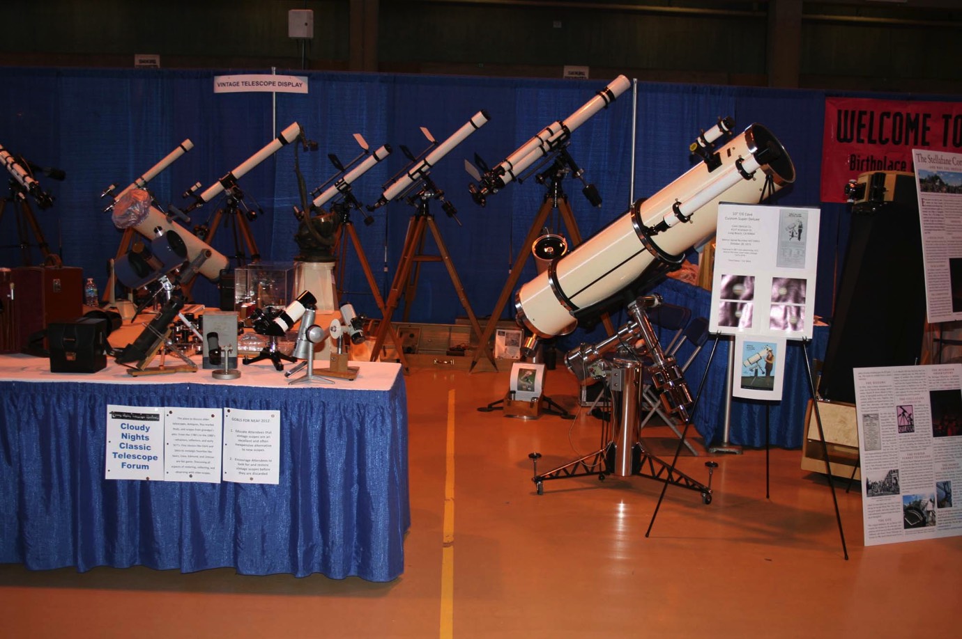
One further episode in this Cave’s history. In April 2012 several members of the Cloudy Nights Classic Telescope forum got together to put on a display of Classic telescopes at the North East Astronomy Forum (NEAF) put on by Rockland Astronomy Club at Rockland Community College in Suffern, NY.
In addition to several classic refractors, reflectors and SCTs, this Cave made a beautiful addition to the display. It has had many miles under its belt travelling around the country from Cave Optical Co. to various owners and this great trip to NY added a few more.
In addition to several classic refractors, reflectors and SCTs, this Cave made a beautiful addition to the display. It has had many miles under its belt travelling around the country from Cave Optical Co. to various owners and this great trip to NY added a few more.